Industrial Stations EE 8000 Connection and Settings
3.1/0614 23
Connection of Modules
The different modules are connected with the PCB of the basic housing EE 8999M / the expansion
housing EE 8999S, by means of a ribbon cable.
For each module place an appropriate connector is available (module place top position / centre
position / bottom position, see “
Connection and Settings”).
Only the loudspeaker module (EM 650) is connected to the PCB (of the EE 8999M) by means of two
wires (terminals “LS+“ and “LS–“, this means no ribbon cable is used).
Note: The loudspeaker module can be installed in the expansion housing EE 8999S (as well as in the
empty housing EDI 600), but it has to be connected to the EE 8999M. The wires for the connection of
the EM 650 can be led through the respective expansion openings of the housing (therefore the expan-
sion openings have to be broken out previously).
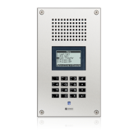
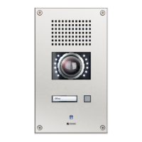
EE 8999M: Possible positions of the modules
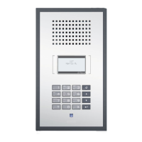
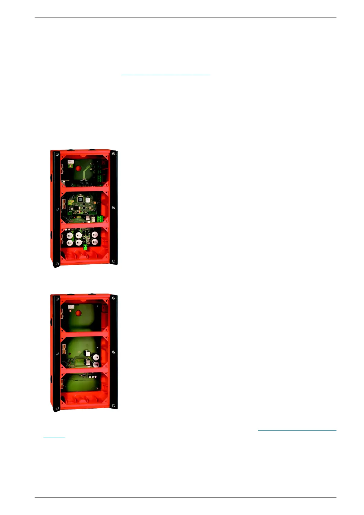
EE 8999S: Possible positions of the modules
Note: For detailed information regarding possible positions of modules, see ”Module Positions” on
page 11.
Top module place:
■
Loudspeaker module
■
Button module
■
Dummy module
Centre module place:
■
Button module
■
Dummy module
Bottom module place:
■
Microphone module
■
Button module
■
Dummy module
Top module place:
■
Loudspeaker module
(connected to EE 8999M)
■
Button module
■
Dummy module
Centre module place:
■
Button module
■
Dummy module
Bottom module place:
■
Button module
■
Dummy module