Connection and Settings Industrial Stations EE 8000
24 3.1/0614
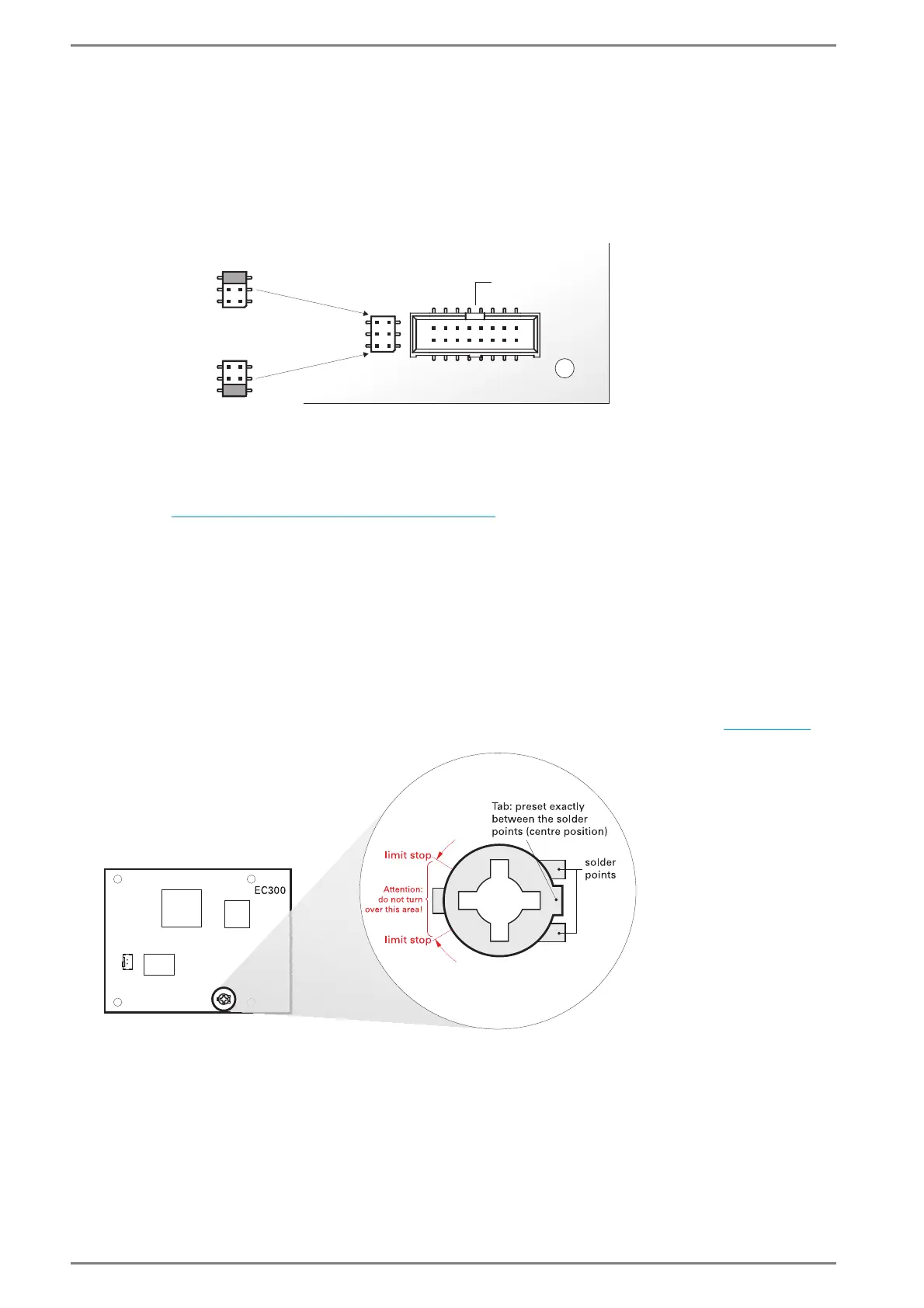
Jumper for Microphone Modules
For use of the different microphone modules, the correct jumper positions must be set at the 6-way pin
connector on the PCB of the EE 8999M (next to the 16-way connector for the bottom position module).
This means in more detail:
The microphone modules EM 680, EM 681 must be supplied with a LED voltage of 5 V.
The microphone modules EM 660, EM 6B0 must be supplied with a LED voltage of 18 V.
Note:
In standard (default) the jumpers are set for supply of microphone modules EM 680 and EM 681
(this means 5 V LED).
If microphone modules EM 660 or EM 6B0 are in use, then the button module EM 605 cannot be
used, see ”
Mounting Button Modules” on page 19.
Attention: If the microphone modules EM 680 and EM 681 are supplied with 18 V LED, then a defect
of the LED driver may occur, as the driver is not specified for such a high voltage (18 V).
Potentiometer for Microphone Sensitivity
The potentiometer for the microphone sensitivity is preset as shown in the picture below (center posi-
tion).
Attention: The (pre)setting of the potentiometer should not be changed! When the microphone sen-
sitivity must be changed, the settings have to be carried out via programming in CCT, see page 32
.
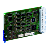
EE 8999M
18 V LED
5 V LED
18 V LED
JP
JP
jumper for modules
EM 680, EM 681
(default)
jumper for modules
EM 660, EM 6B0
connector for module
at bottom position