Do you have a question about the Commend EE 8000 and is the answer not in the manual?
Details about digital 2-wire technology, speech power, volume control, microphone sensitivity, modular construction, ruggedness, and handset connectivity.
Explains the flexible, customer-specific configuration of digital heavy industrial stations using modules for dialling, buttons, microphones, and loudspeakers.
Describes how individual module combinations derive the type designation of the configured industrial station.
Lists codes for modules like Dummy, Loudspeaker, Button, and Microphone, with their respective types.
Lists housing codes like Empty, Basic, and Expansion, with their respective types.
Details basic housing EE 8999M and EE 8999M-SOS, with 3 module slots and electronics.
Describes expansion housing EE 8999S with 3 module slots, electronics, and expansion openings.
Details the empty housing EDI 600, used for cable distributors or additional electronics.
Introduces the 11 different modules available for the modular concept of the digital heavy industrial series EE 8000.
Describes the Loudspeaker module EM 650 for industrial stations, detailing its technical data and features.
Details the Button module EM 602 with buttons 1-6 for a full keypad, programmable with various functions.
Details the Button module EM 603 with buttons 7-X for a full keypad, programmable with various functions.
Details the Button module EM 606 with 6 direct dialling buttons, programmable with various functions.
Details the Button module EM 605 with 6 LED direct dialling buttons, programmable with various functions.
Details the Microphone module EM 660 with universal microphone and 2 buttons, supporting omnidirectional and noise-cancelling.
Details the Microphone module EM 680 with universal microphone and 2 LED buttons, supporting omnidirectional and noise-cancelling.
Details the Microphone module EM 681 with a 1 LED button and a red mushroom button with 'SOS' print.
Details the Microphone module EM 6B0 with a conversation lamp and a red mushroom button with 'SOS' print.
Details the Dummy module EM 600 for filling empty module slots or fitting customer specific buttons.
Details the Dummy module EM 6A0 with 'SOS' print for filling empty module slots.
Provides a table showing module compatibility across EE 8999M, EE 8999S, and EDI 600 housings.
Introduces the 4 different standard stations of the EE 8000 series.
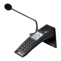
Details the Industrial master station EE 8158M with 6 programmable LED buttons, loudspeaker, and microphone.
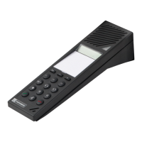
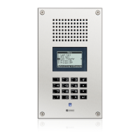
Details the Industrial master station EE 8238M with a full keypad, microphone, and 2 LED buttons.
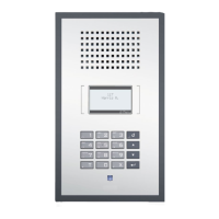
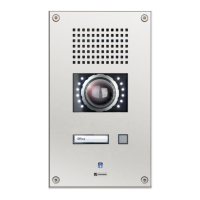
Details the Industrial sub-station EE 81ADMSOS with 'SOS' print, loudspeaker, microphone, and buttons.
Provides detailed dimensional drawings and measurements for the industrial station in mm and inches.
Guidance on mounting stations and combinations to ensure the microphone is at 1.40 m (4.6 ft) above the floor.
Specifies the mounting height for horizontal station arrangements and single units relative to the finished floor.
Specifies the mounting height for vertical station combinations of 2 or 3 units relative to the floor.
Warning about exposing the station to extreme temperatures, specifying operating limits.
Recommendation for outdoor mounting: cutting out water outlets on the bottom of the housing.
Instructions for mounting housings (EE 8999S to EE 8999M) using the EE 8999-KIT mounting material.
Step-by-step guide for horizontal mounting of combined housings, detailing bracket and ring placement.
Step-by-step guide for vertical mounting of combined housings, detailing bracket and ring placement.
Illustrates the mounting example for combining EE 8999M and EE 8999S housings.
Instructions for mounting cable glands, including cutting gaskets and fastening the gland.
General mounting instructions for modules with housings Rev. 'BA' and 'BB'.
Detailed steps for mounting modules in housings Rev. 'BA', including brackets and connectors.
Detailed steps for mounting modules in housings Rev. 'BB', including screwing and connecting.
Specific installation guidelines for microphone modules in basic housing EE 8999M, bottom module place only.
Installation guidelines for loudspeaker module EM 650 in EE 8999M, EE 8999S, and EDI 600 housings.
Installation guidelines for button modules in EE 8999M and EE 8999S housings, including compatibility note.
Installation guidelines for dummy modules in EE 8999M, EE 8999S, and EDI 600 housings.
Diagram and description of the PCB layout for EE 8999M, showing module places and connections.
Details on connecting terminals A, B to a subscriber card of the Intercom Server.
Specifies power supply requirements (AC/DC) and connection terminals for the industrial station.
Describes the function of terminals OUT1/OUT1 and OUT2/OUT2 as relay outputs.
Explains how to connect the expansion housing EE 8999S to the EE 8999M and other EE 8999S units.
Provides guidelines for grounding the Intercom Server in environments with heavy electromagnetic interference.
Suggests using ferrite cores and shielded twisted pair cables for interference reduction.
Illustrates a grounding example for the central power supply unit and terminal block connections.
Explains how modules are connected via ribbon cable to the housing PCB, and specific wiring for loudspeaker.
Lists the possible module placements (top, centre, bottom) for the EE 8999M housing.
Lists the possible module placements (top, centre, bottom) for the EE 8999S housing.
Details jumper settings on the EE 8999M PCB for different microphone modules (EM 660, EM 6B0, EM 680, EM 681).
Explains the preset potentiometer for microphone sensitivity and advises against changing it without CCT programming.
Diagram and explanation of handset connections, including loudspeaker, microphone, and PTT button functionality.
Covers subscriber and station properties, and available configuration tabs like Inputs, Outputs, and General.
Explains activation of internal inputs/outputs and setting of call numbers for configuration.
Details settings for number of modules, idle state colours, brightness, and compatibility mode.
Explains programming methods: predefined functions and manual button/indication functions.
Describes using predefined functions for common tasks like direct dialling and call request indication.
Explains how to manually adapt predefined functions for buttons and their indications.
Details the unique numbering system for buttons and LEDs for programming in CCT.
Describes creating templates for LED indications of conversations, call requests, inputs, outputs, and line faults.
Defines templates for conversation colour, blink mode, and busy subscriber indication.
Defines templates for call requests (call 1, call 2) and input messages, including colour and blink mode.
Defines templates for outputs and special functions, specifying colour and blink mode for conditions 1-4.
Defines separate indications for station and input line faults, including colour and blink mode.
Explains how to use predefined functions for modules like direct dialling and call request indication.
Details how to configure direct dialling buttons for calls, conversations, and LED feedback.
Explains programming a single button for press and release actions, and its standard behaviour.
Details programming outputs to be active, off, toggled, or blinked, with LED feedback.
Explains simulating input levels ('short' or 'open') by pressing or releasing a button.
Details how to configure buttons to trigger input messages, with LED and buzzer feedback.
Provides manual configuration options for direct dialling, single buttons, outputs, input simulation, and input messages.
Explains the need for higher volume in industrial stations and how to set volume via CCT 800.
Describes defining two volume modes (High, Low) for varying ambient noises, either automatic or manual.
Explains how the station monitors noise levels to automatically activate volume modes and switch to 'Low' when a button is pressed.
Details CCT settings for microphone sensitivity (internal/external) and voice control thresholds.
Describes manual volume switching via dialling codes and the conditions for using the volume control button.
Warning about configuring both automatic and manual volume control, and programming output '9T92'.
Presents recommended settings for Simplex, Duplex, and Open Duplex modes based on practical tests.
Recommended settings for loudspeaker and microphone in Simplex mode, considering background noise.
Recommended settings for loudspeaker and microphone in Duplex mode, including high volume duplex mode.
Recommended settings for loudspeaker and microphone in Open Duplex mode, considering external sound projectors.
Provides the website address for more information about products and services.
| Brand | Commend |
|---|---|
| Model | EE 8000 |
| Category | Intercom System |
| Language | English |