bit
5:-selects
active
color
set
in
320
x
200
4 colors
or
640
x
200
4 colors
mode
bit
6-7:
unused
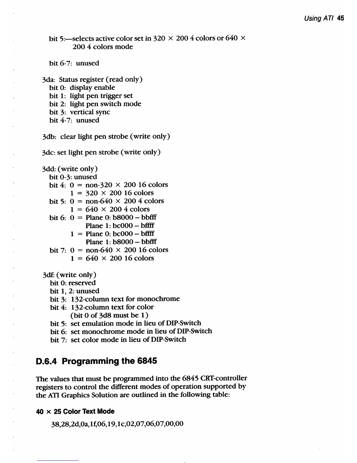
3da: Status register
(read
only)
bit
0: display enable
bit
1:
light
pen
trigger
set
bit
2:
light
pen
switch
mode
bit
3:
vertical sync
bit
4-7:
unused
3db: clear light
pen
strobe
(write
only)
3dc:
set
light
pen
strobe
(write
only)
3dd:
(write
only)
bit
0-3:
unused
bit
4: 0 = non-320 x
20016
colors
1
=
320
x
200
16
colors
bit
5:
0 = non-640 x
200
4 colors
1
=
640
x
200
4 colors
bit
6: 0 = Plane
0:
b8000
- bbfff
Plane
1:
bcOOO
- bffff
1
= Plane 0:
bcOOO
- bffff
Plane
1:
b8000
- bbfff
bit
7: 0 = non-640 x
20016
colors
1
=
640
x
200
16
colors
3df:
(write
only)
bit
0: reserved
bit
1,
2:
unused
bit
3:
132-column
text
for
monochrome
bit
4:
132-column
text
for
color
(bit
0
of
3d8
must
be
1)
bit
5:
set
emulation
mode
in
lieu
of
DIP-Switch
bit
6:
set
monochrome
mode
in
lieu
of
DIP-Switch
bit
7:
set
color
mode
in
lieu
of
DIP-Switch
0.6.4 Programming the 6845
The
values
that
must
be
programmed
into
the
6845
CRT-controller
registers
to
control
the
different
modes
of
operation
supported
by
the
ATI
Graphics Solution are outlined
in
the
following table:
40 x
25
Color
Text
Mode
38,28,2d,0a, If,06, 19, 1 c,02,07,06,07,00,00
Using
Art
45