ADCP-90-545 • Issue 4 • July 2016
Page 22
© 2016 CommScope. All Rights Reserved.
Use the following procedure to prepare and install the cable.
1. Determine whether a cable clamp or compression
fitting will be used to hold the cable. In
general, a cable clamp is intended for a larger diameter cable, but either method can be
used for securing the cable.
2. Strip the outer sheath of the cable to expose the inner fiber bundles. Figure 16 and
Figure 17 show the correct breakout for
termination. Figure 18 shows the correct breakout
for splicing. The cable sheath sho
uld extend about 0.75 inch (1.9 cm) beyond the cable
clamp or compression fitting.
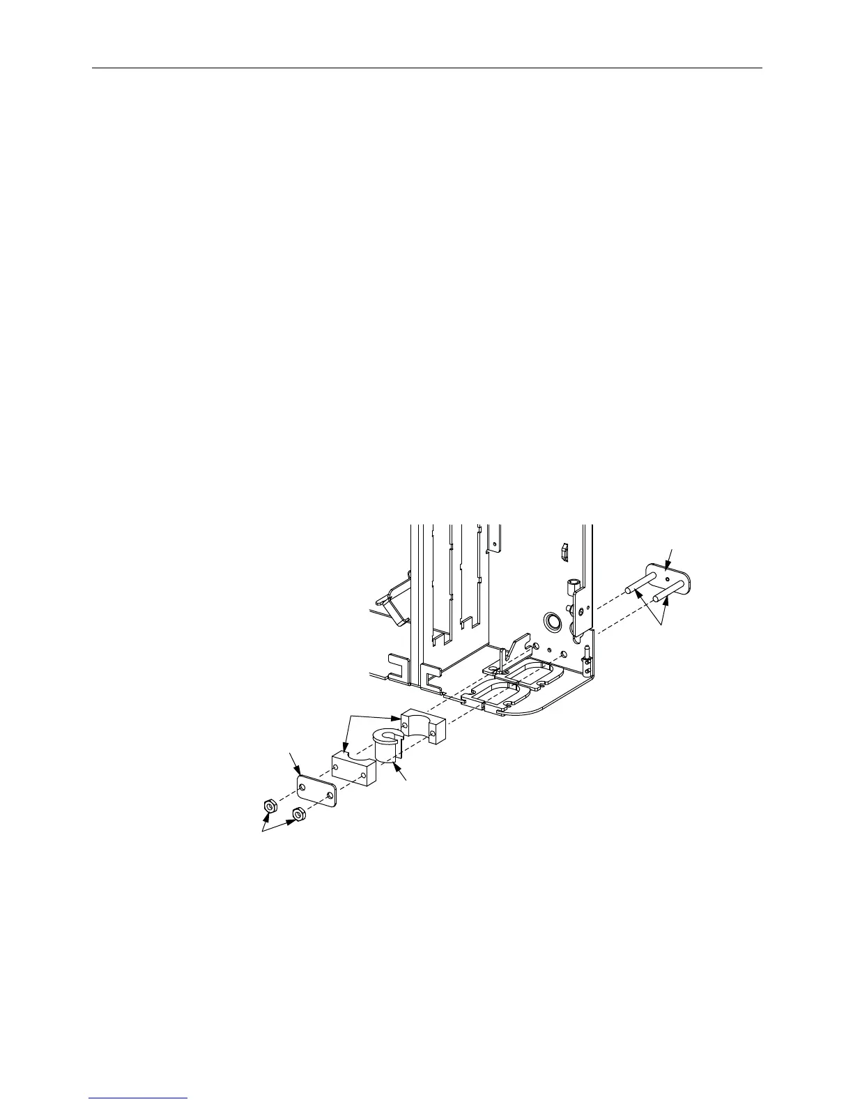
3. If using a cable clamp (Figure 19):
a. Before mounting the wall-mount chassis to the
wall, determine which of the four
available mounting locations will be used and install the clamp bracket by inserting the
two integral bolts from the rear, as shown. If the cable is routed to the wall box from
above, install the cable clamp bracket in the upper part of the box. If the cable is routed
to the wall box from below, install the cable clamp bracket in the lower part of the box.
b. Sort through the rubber grommets in the kit and find the
one that best fits the cable. If
the cable is too small to fit snugly in the smallest grommet, build up the cable with
tape of a suitable material per local standards.
c. Assemble the cable clamp components on the integral bolts in the order shown in the
figu
re and secure with the two nuts provided.
CLAMP
BRACKET
INTEGRAL
BOLTS
CLAMP
YOKES (2)
RUBBER
GROMMET
PLATE
NUTS (2)
24566-A
Figure 19. Cable Clamp Assembly (Select from Four Mounting Locations)