4. Design and functioning
20
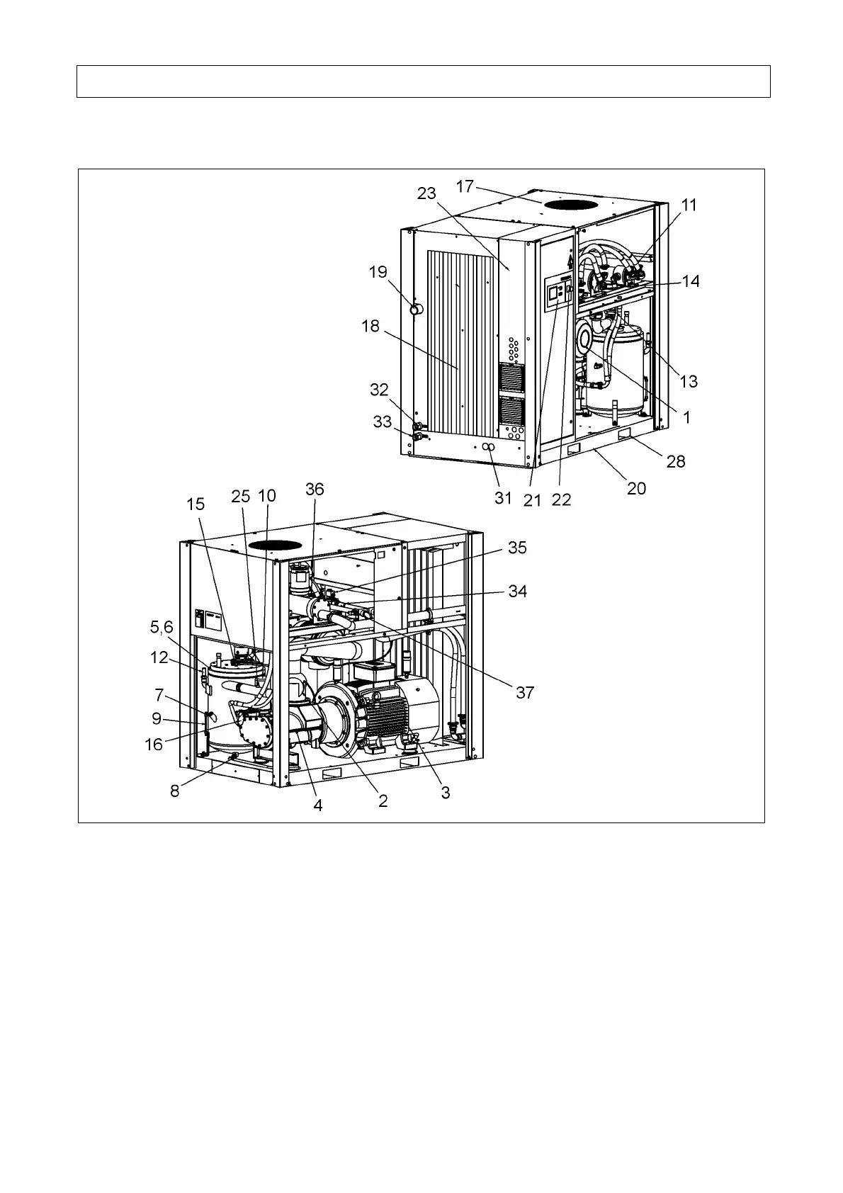
4.1.2 Design of water-cooled units
Fig. 3
1 Intake filter
2 Intake regulator
3 Electric motor
4 Screw compressor
5 Pressure reservoir
6 Oil fine separator
7 Oil filling port
8 Oil drain
9 Oil level indicator
10 Oil filter
11 Oil cooler
12 Safety valve
13 Pressure holding and check valve
14 Air cooler
15 Oil fine separator extractor
16 Oil temperature regulator
17 Cooling air ventilator
18 Cooling air inlet filter mat
19 Compressed air outlet
20 Base frame
21 Control keypad
22 EMERGENCY OFF push-button
23 Control cabinet
24 Supply cable gland
25 Final compression temperature
sensor
26 Network pressure sensor
27 Final compression pressure sensor
28 Opening for lifting gear
29 Fan protection panel
30 Pressure relief for cooler
31 WRG heat-recovery connection
(option)
32. Cooling water inlet (Lxx W only)
33. Cooling water outlet (Lxx W only)
34. Dirt interceptor (Lxx W only)
35. Cooling-water solenoid valve
(Lxx W only)
36. Regulating valve (Lxx W only)
37. Monitoring cooling-water
temperature (Lxx W only)