EasyManuals Logo

CompAir L18FS User Manual

CompAir L18FS
72 pages
To Next Page IconTo Next Page
To Previous Page IconTo Previous Page
Page #24 background imageLoading...
Page #24 background image
4. Design and functioning
22
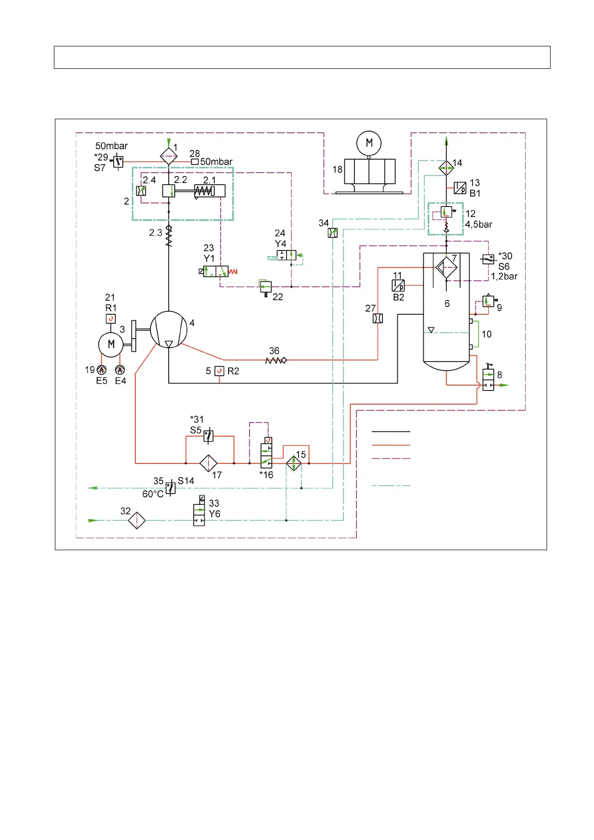
4.2.2 Schematic diagram L140
Fig. 5
1
Intake filter
2
Intake regulator
2.1 Actuator
2.2 Throttle valve
2.3 Check valve
2.4 Choke valve, adjustable
3
Electric motor
4
Compressor block
5
Final compression temperature
sensor (R2)
6
Pressure reservoir
7
Fine separator
8
Oil drain
9
Safety valve
10
Oil level indicator
11
Final compression pressure
sensor
12
Pressure holding and check
valve
13
Network pressure sensor
14
Air cooler
15
Oil cooler
16
Oil temperature regulator
17
Oil filter
18
Cooling air ventilator
19
Motor lubrication system E4, E5
21
Motor temperature (R1)
22
Pressure regulator
23
3/2-way solenoid valve (control
valve) (Y1)
24
Blow-off valve
27
Choke valve
28
Intake monitor, visual
29
Intake filter monitor (S7) *)
30
Fine separator monitor (S6) *)
31
Oil filter monitor (S5) *)
32
Dirt interceptor (Lxx W only)
33
Cooling-water solenoid valve
(Y6) (Lxx W only)
34
Manual regulating valve
(Lxx W only)
35
Monitoring cooling-water
temperature (S14) (Lxx W only)
*)
Option
Compressed air line
Oil line
Control line
Cooling water line
(only LxxW - water-cooled units)

Table of Contents

Questions and Answers:

Question and Answer IconNeed help?

Do you have a question about the CompAir L18FS and is the answer not in the manual?

CompAir L18FS Specifications

General IconGeneral
BrandCompAir
ModelL18FS
CategoryAir Compressor
LanguageEnglish

Related product manuals