Technical Reference Guide
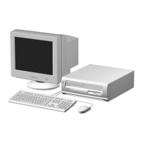
Compaq Deskpro 4000 and 6000 Personal Computers
featuring the Pentium II Processor
First Edition – October 1997
2-7
2.3.3 SYSTEM BOARD LAYOUTS
Item Function
1 Top: Line In (audio) connector Bottom: Line Out (audio) connector
2 Top: Mic In (audio) connector Bottom: Headphones Out (audio) connector
3 Top: Mouse I/F connector Bottom: Keyboard I/F connector
4 Top: Serial I/F (B) connector Bottom: Serial I/F (A) connector
5 Top: Universal Serial Bus (port 2) connector Bottom: Universal Serial Bus (port 1) connector
6 InfraRed I/F connector
7 Network Interface connector (RJ-45)
8 Header for AUI network interface connector
9 Top: Parallel I/F connector Bottom: SCSI connector
10 AGP connector
11 SCSI connector
12 CD-ROM audio input connector
13 Power switch/LED header
14 Power supply connector
15 IDE connector (secondary, CD-ROM drive (if installed))
16 Diskette drive connector
17 IDE connector (primary, hard drive (4000 models))
18 Alternate fan header (for upgrade processors w/integrated fan)
19 Battery replacement header
20 Pentium II SEC cartridge (in processor slot)
21 DIMM sockets
22 Bus/core ratio select DIP switch
23 Battery
24 Riser (backplane) card sot
25 SIMM sockets
26 Network I/F upgrade connector
27 Frequency select DIP switch
28 Network I/F connector (BNC)
NOTES:
[1] Board p/n 006650-xxx shown here for identification only. See note at beginning of chapter 1.
Figure 2–6.
System Board Layout, Component Side
System Board p/n 006627-xxx
1 3
4
5
2 7
12
13
14
11
8
15
9
10
16
18
17
6
System Board p/n 006650-xxx [1]
9
4
17
15
14
16
20
6
23
22
26
27
24
21
19
20
19
22
23
25
24
28
37
 Loading...


