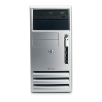
Technical Reference Guide
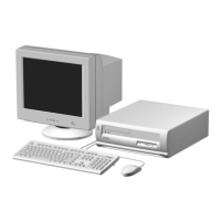
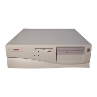
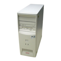
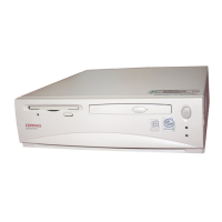
Compaq Deskpro 4000 and 6000 Personal Computers
featuring the Pentium II Processor
First Edition–- October 1997
4-9
4.2.5 PCI INTERRUPT MAPPING
The PCI bus provides for four interrupt signals; INTA-, INTB-, INTC-, and INTD-. These
signals may be generated by on-board PCI devices or by devices installed in the PCI slots. In
order to minimize latency, INTA-..INTD- signal routing from the slots to the system board is
distributed evenly by the riser card (backplane) as shown below:
System Board PCI Slot 1 PCI Slot 2 PCI Slot 3 PCI Slot 4 [1]
INTA- INTD- INTB- INTC- INTA- [2]
INTB- INTA- [3] INTC- INTD- INTB-
INTC- INTB- INTD- INTA- INTC-
INTD- INTC- INTA- [4] INTB- INTD-
NOTES:
[1] Minitower only
[2] Shared with network interface controller
[3] Shared with SCSI controller
[4] Shared with USB controller
Interrupts generated by PCI devices can be configured to share the standard AT (IRQn) interrupt
lines. Two devices that share a single PCI interrupt must also share the corresponding AT
interrupt. Example: If a PCI card is installed in slot 5 and wants to use INTA- then it must share
INTA- as well as the corresponding AT interrupt with the on-board network interface controller.
Three PCI configuration registers are used to route the INTA-..INTD- signals to the IRQn signal
lines (refer to section 4.3.4.1 for information on IRQn routing). The power up (default)
configuration has PCI interrupt redirection disabled.
 Loading...


