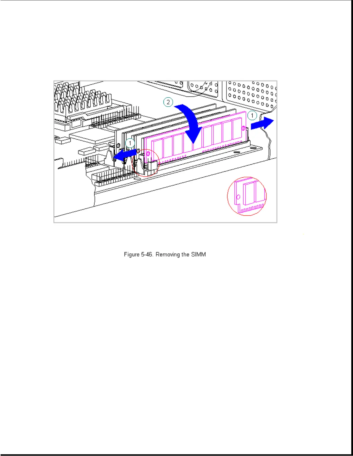
3. Push out on the SIMM slot latches and tilt the SIMM 45 degrees from
vertical and slide the SIMM out of its slot (Figure 5-46).
The notch on the left end of the SIMM (Figure 5-46) serves as an
orientation indicator. Use this notch as a guide to orient the SIMM
properly and reverse the above procedure to install a SIMM.
Chapter 5.16 Processor
The processor for the computer is mounted in a ZIF socket on the system
board as shown in Figure 5-47 and Figure 5-48.
IMPORTANT: On 586-based system boards, the heat sink retaining clip must
be released before actuating the processor eject lever.
To replace a processor, complete the following steps:
1. Complete the steps in Section 5.3 to prepare the computer for
disassembly.
2. Complete the steps in Unit Cover Removal and Replacement in Section 5.4
to gain access to the system board.
 Loading...