PM1323
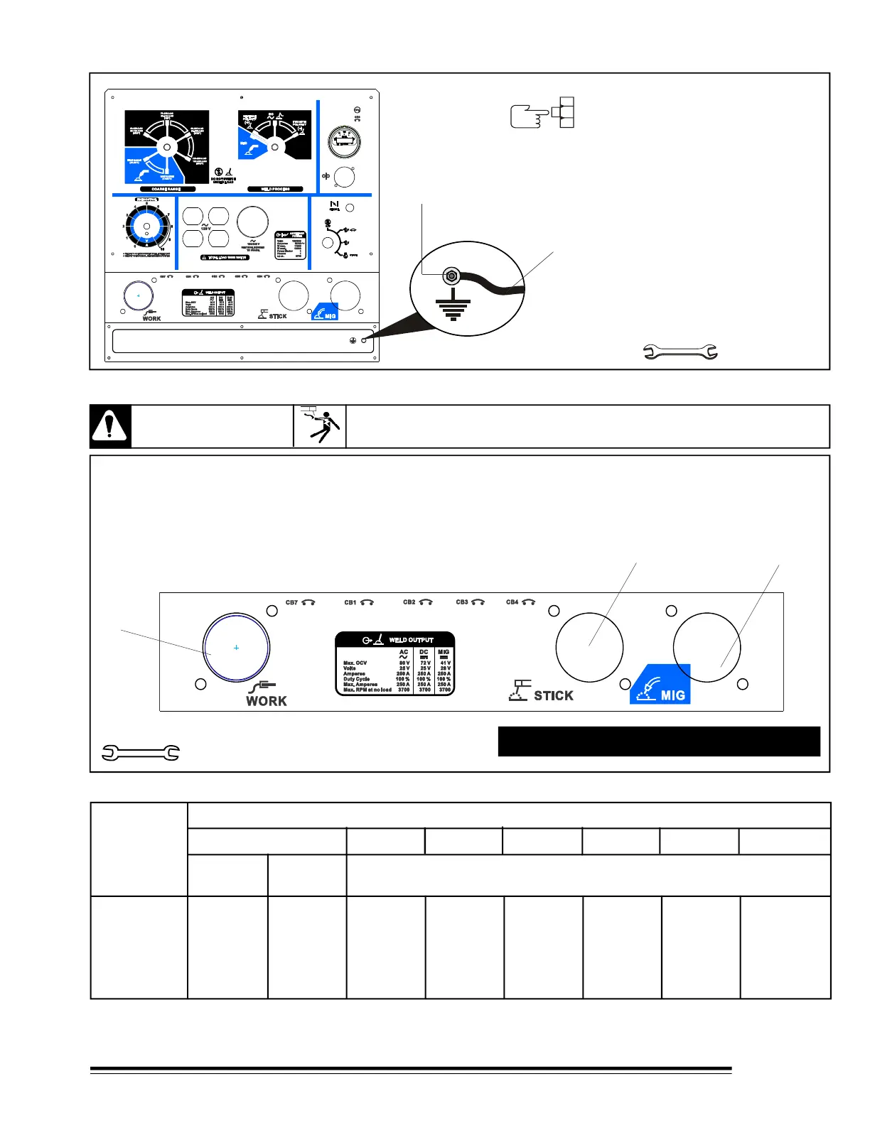
3-6 CONNECTING TO GROUND THE WELDING GENERATOR
11.1mm (7/16")
1. Generator Grounding Terminal.
TOOLS NEEDED
For to use MIG, connect Work cable at Work
terminal and wire feeder to MIG terminal.
For to use STICK, connect Work cable at Work
terminal and electrode cable to STICK terminal.
1 Work Terminal.
2 Constant Current Terminal (STICK).
3 Constant Voltage Terminal (MIG).
Use only 2 terminals at same time.
19 mm (3/4")
Tools needed
3-7 CONNECTING OUTPUT TERMINALS
WARNING
READ SAFETY BLOCKS at beginning of manual before proceeding.
100
150
200
250
300
350
4
3
3
2
1
1/0
4
3
2
1
1/0
2/0
4
2
1
1/0
2/0
3/0
3
1
1/0
2/0
3/0
4/0
2
1/0
2/0
3/0
4/0
2-2/0
1
2/0
3/0
4/0
2-2/0
2-3/0
1/0
3/0
4/0
2-2/0
2-3/0
2-3/0
1/0
3/0
4/0
2-2/0
2-3/0
2-4/0
* Weld cable size (AWG) is based on either a 4 volts or less drop or a current density of not more than 300 circular mils
per ampere. Use weld cable with insulation rating equal to or greater than the open-circuit voltage of the unit.
TABLE 3-1 SELECTING WELD CABLES SIZE.*
WELDING
AMPERES
10 to 60%
Duty Cycle.
60 Thru
100%
Duty Cycle.
100 Ft (30 m) or less 150Ft (45 m) 200Ft (60 m) 250Ft (75 m) 300Ft (90 m)
400Ft (120 m)
350Ft (105 m)
10 thru 100% Duty Cycle
TOTAL CABLE (COPPER) IN CIRCUIT OF WELD *
2. Use 10 AWG cable size or large,
to grounding
This point is connected to
welding generator structure.
F-0352
REV. A
GROUND
6