PM1323
The auxiliary force decreases as the welding current
increases.
Set the fin tuning for maximun R1 in 10 auxiliary output.
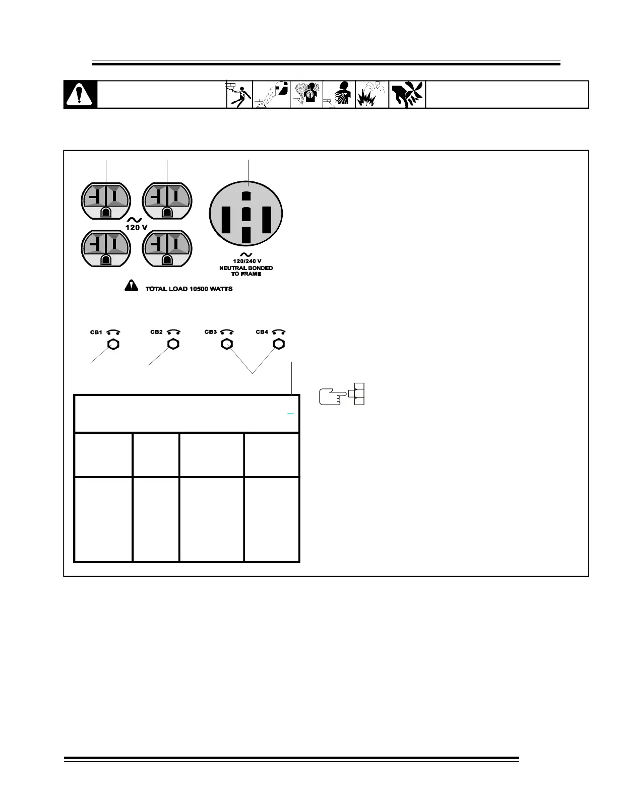
1.- Receptacle of 120 V, 20 Amp (RC1)
2.- Receptacle of 120 V, 20 Amp (RC2)
RC1 and RC2 to 60 Hz single phase power supply . The
maximum output RC1 or RC2 is 2.4kVA / kW
3.- Receptacle of 120V/240 V, 50 Amp (RC3)
4.- Circuit Reset (CB1)
5.- Circuit Reset (CB2)
CB1 Protect RC1 AND CB2 protect RC2 of overload. If
operating CB1 , RC1 not work, and if operating CB2 , RC2
does not work.
Press the button to reset CB1 or CB2
6.- circuit Reset CB3 AND CB4
CB3 and CB4 protect RC1, RC2 and RC3
The combined power of all receptacles is limited to
10.0kVA /kW nominal generator
Example: If 20 A. is draw from each 120V duplex
receptacle, only 23.0 A. is available at the 120 / 240 V.
receptacle.
2 ( 120 V x 20 A ) + ( 240 V x 23 A) = 10.5 kVA / kW.
7.- Label auxiliary force while welding
5-1 RECEPTACLES
4
Weld
Current
Watts
*120 V Duplex
Receptacle
(Amperes)
120/ 240 V
Receptacle
(Amperes)
0
90
125
10500
8000
5200
44*
33
21
87*
66*
43*
WELD & AUXILIARY POWER SIMULTANEOUS
OUTPUT
*In Receptacle 120 / 240 V 50 A (RC3)
CAUTION
READ SAFETY BLOCKS at beginning
of manual before proceeding.
SECTION 5 AUXILIARY POWER
12