4 Control Elements and Display
The display is an 8 digit 14-segment-LCD.
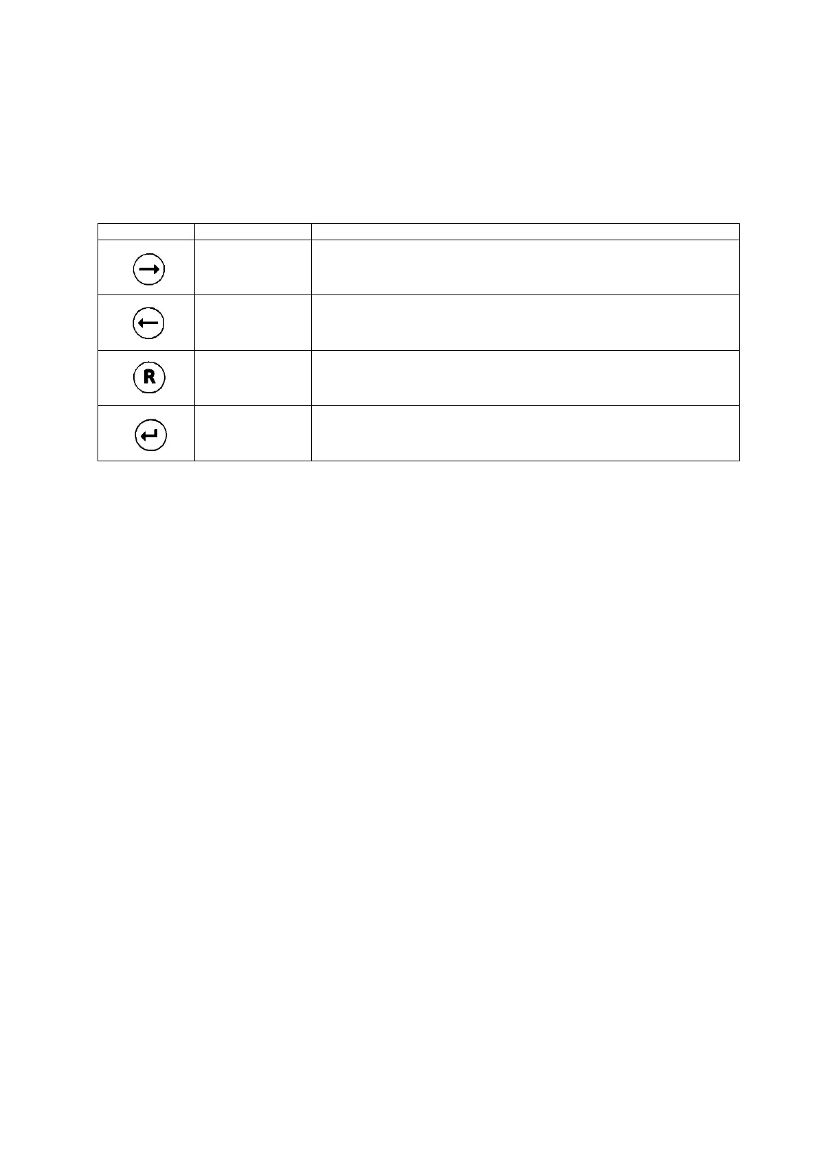
You can program the sensor head by holding the magnetic pin on the control buttons:
Increase value.
Navigate to the right.
Push and hold the contact for speed mode.
Decrease value.
Navigate to the left.
Push and hold the contact for speed mode.
Navigate backwards.
Change entry.
5 Start up
After connecting the sensor head to power, it performs a self–test and after a few seconds displays
the software index.
Remove the yellow protection cap from the sensor cover.
Install the sensor and the dust filter which is included in the sensor package. Find more details in
chapter 7.
After the sensor has been plugged in, the sensor head reads the sensor parameters and displays the
parameter set index, the target gas, the measuring range and the best-before date of the sensor in the
format week / year. After zero has stabilized, the sensor head goes into the measuring mode.
If you plug in another sensor type as before, the display shows NEW TYPE. Confirm this with ENTER.
Otherwise remove the sensor and plug in the right type.
As long as the sensor head has not gone into the measuring mode, it is in the ERROR mode.
(0 mA signal in 3–wire operation, 2 mA in 2–wire operation)
Once the sensor head has started the measuring mode you can program the real time clock (chapter
6.2) and the service mode setting (chapter 6.3).
Some sensors do require a certain warm–up time until zero has stabilized. If sensor and sensor head
have different temperatures, allow enough time to equalize. 1 hour after installation a zero adjustment
should be done (chapter 6.4).