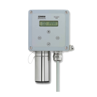
Statox 506 Sensor Head
Operations Manual
Page
1 SAFETY INSTRUCTIONS 3
2 STATOX 506 CONSTRUCTION 4
3 INSTALLATION AND CONNECTION 5
3.1 Installation 5
3.2 Electrical Connection 6
3.2.1 Statox 506 cable connection 7
3.2.2 Connection diagram with Statox 502/503 Control Module in the 2-wire mode 9
3.2.3 Connection diagram with Statox 502/503 Control Module in the 3-wire mode 10
4 CONTROL ELEMENTS AND DISPLAY 11
5 START UP 11
6 MENU 13
6.1 Main Menu 13
6.2 Setting the Real Time Clock 15
6.3 Current Output in the Service Mode 16
6.4 Sensor Calibration 17
6.5 Prooftest 19
6.6 Info Menu 20
6.7 Test Menu 22
7 SENSOR REPLACEMENT 22
8 MAINTENANCE AND CLEANING 24
9 ACCESSORIES AND SPARE PARTS 24
10 STATUS- AND ERROR MESSAGES 25
10.1 Status Messages 25
10.2 Error Messages 27
11 FUNCTIONAL SAFETY 28
11.1 Safety Function 28
11.2 Diagnostic Time and Measuring Cycle 28
11.3 Installation and Parameter Settings 28
11.4 Maintenance Schedule 28
11.5 Repair and Spare Parts 28
11.6 Failure Rates and Safe Failure Fraction 29
11.7 Average Probability of Failure on Demand 29
11.8 Classification of the Safety Integrity Level (SIL) 29
11.9 Lifetime 29
12 TECHNICAL DATA 30
12.1 Transmitter General 30
12.2 Sensor Data 30
13 EU-DECLARATION OF CONFORMITY 33