Connect the ground contact to ground. It can take cables up to 4 mm². Reassure proper grounding.
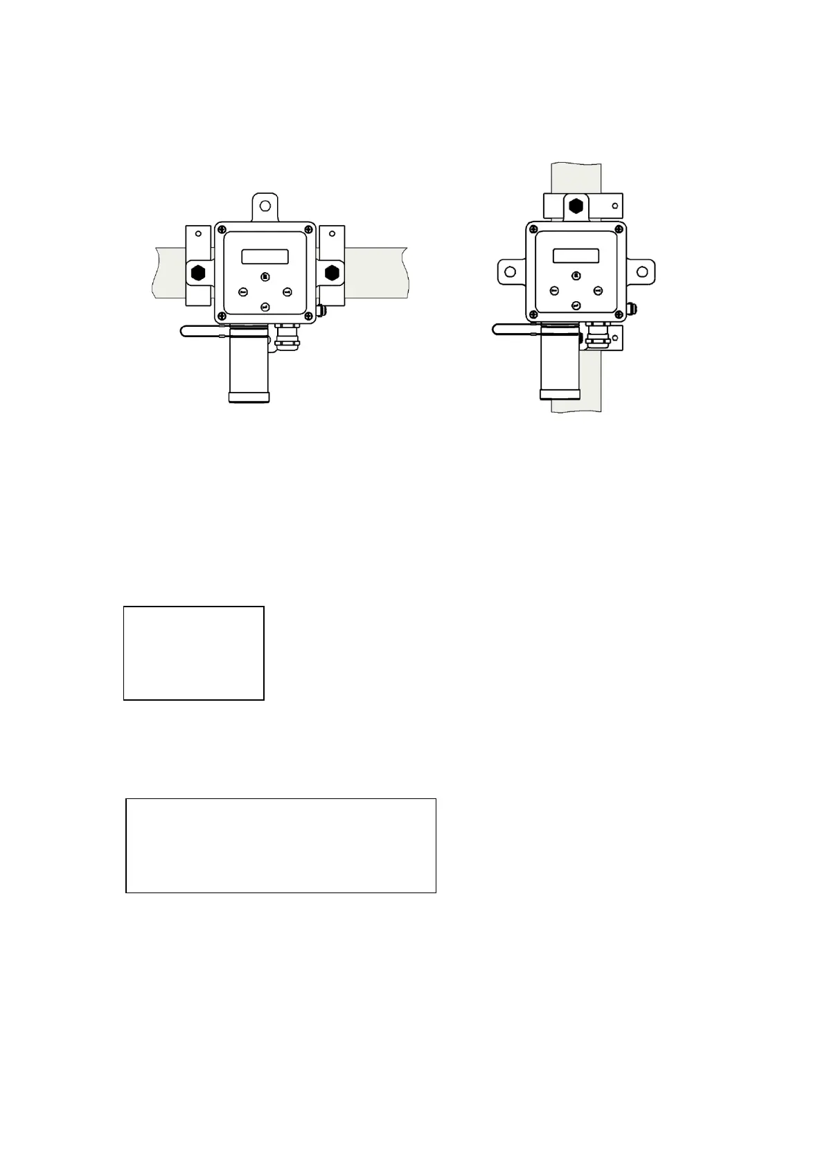
Use the optional pipe kit (see chapter 9) to install the sensor head to horizontal or vertical pipes.
3.2 Electrical Connection
If installed in a classified area, the power supply must run through an intrinsically safe repeater.
The combination Sensor head / repeater / cable must be within these parameters:
Specifications:
U
o
, I
o
, C
o
, L
o
:
Approved repeater specifications.
U
i
, I
i
, C
i
, L
i
: Approved sensor head specifications ( Technical data)
C
L
= Cable capacity in nF/km
L
L
= Cable inductivity in nH/m
l = Cable length in m
The allowable cable length must be calculated from the cable capacity and the inductivity of the sensor
head with this formula:
l
max
= (C
o
- C
i
) / C
L
Recommended cable:
2 x or 3 x 0.5 mm², preferably shielded (e.g. LiYCY).
Terminals: 0.25 – 2.5 mm² (AWG 24 - 12).
The cable gland can accept cables from 4 to 12 mm outer diameter.
U
o
≤
U
i
I
o
≤
I
i
C
o
≥ C
i
+ l
.
C
L
L
o
≥ L
i
+ l
.
L
L
Example:
Cable type LiYCY 0,75mm² : C
L
= 150 nF/km
Repeater: C
o
= 705 nF
Sensor head: Ci = 24 nF
l
max
= 4540 m