Advantage of 3 wire operation:
The signal in the error mode must always be 2 mA when operating in 2 wire installation in order to assure
enough power for the operation.
If you install the sensor head with a 3 wire cable, you can set the current in the error mode to 0 mA. Then
you can set the current in the service mode to 2 mA and thus differentiate between system failure (critical
error) and service mode (non - critical error). This is essential if you operate the Statox 506 as a safety
operated system (SIS). See also chapter 6.3!
If you operate the Statox 506 sensor head with a Statox 502 or 503 Control Module, use the schematics
as shown in chapter 3.2.2 or 3.2.3.
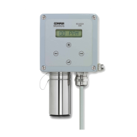
If you operate the Statox 506 sensor head directly on a PCS, use the following diagram.
In case of 2 wire operation use terminal 1 and 2.
Caution:
First complete the electrical connections, then plug the sensor in.
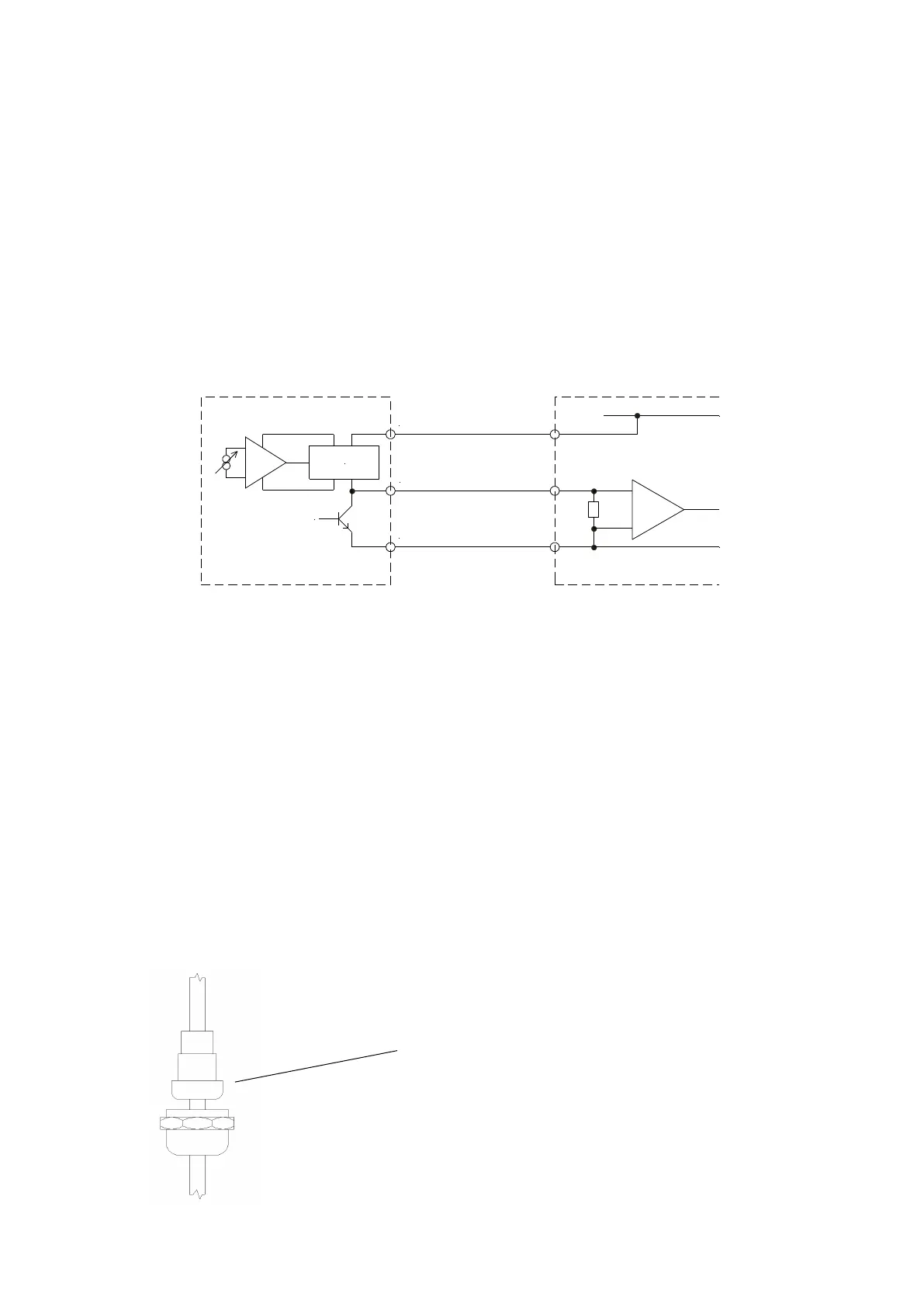
3.2.1 Statox 506 cable connection
Cable specifications see above.
Make sure the sensor is not plugged in!
Remove the nut, the washer set and the metal spring
from the cable gland.
Push the nut and the washer set over the cable end.
The washers have lips which can be removed in order
to widen the inner diameter.