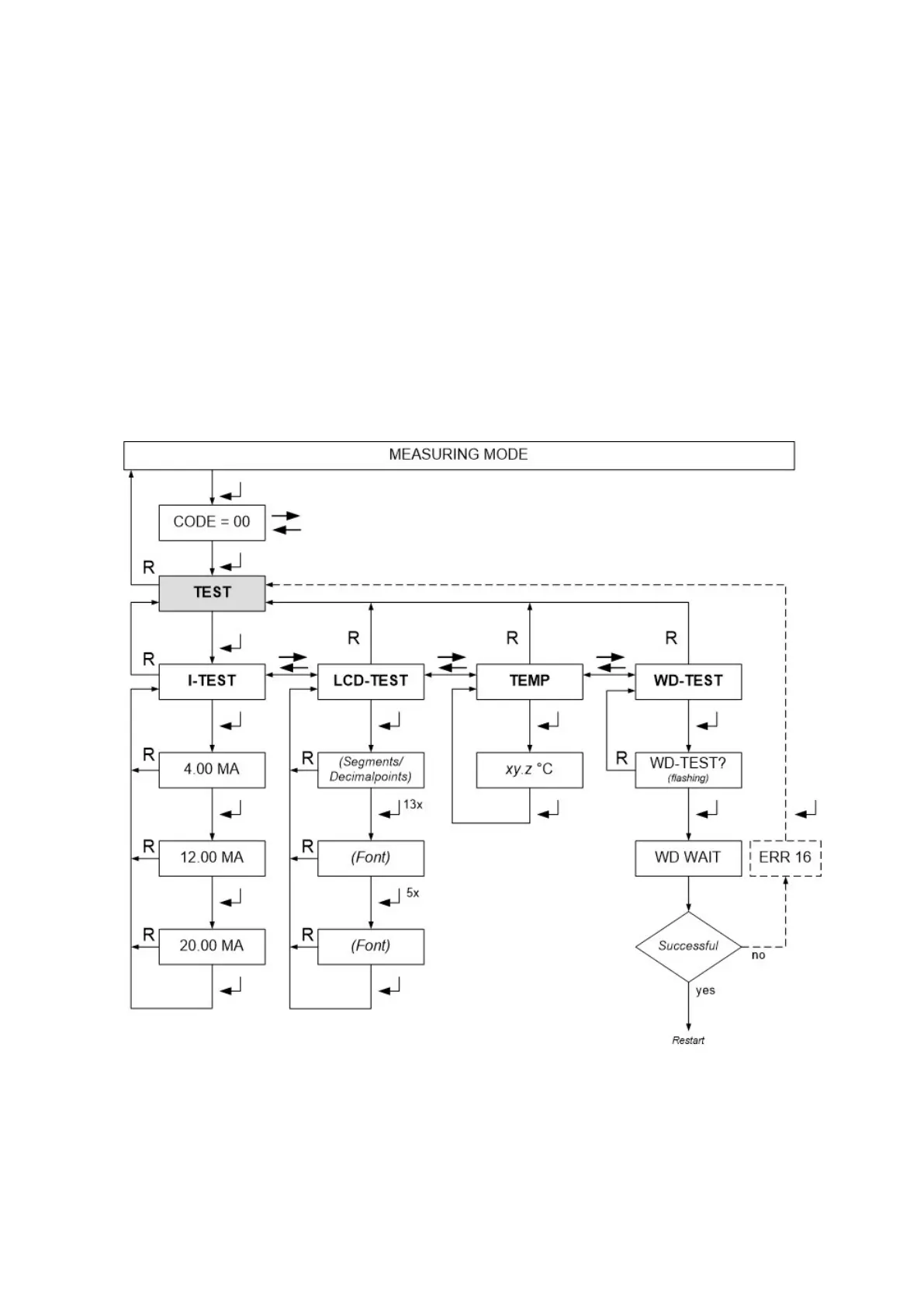
6.7 Test Menu
The test menu helps you testing the sensor head itself and peripheral devices.
Sub menu I-TEST
You can set the analog output current to 4, 12 und 20 mA. Caution: Peripheral alarm devices might be
triggered. Do not create unintended alarms!
Sub menu LCD-TEST
You can create different test - patterns on the display.
Sub menu TEMP
Here you can read the temperature inside the sensor head.
Sub menu WD-TEST
This interrupts the trigger signal for the watchdog. If the watchdog works correctly, it will initiate a restart
of the sensor head. A potential error is shown in the graph below in dotted lines. Error 16 has no timeout,
the service mode will not end.
7 Sensor Replacement
Observe all safety precaution for the handling of electrostatic sensitive material. The sensor must be
removed only in the service mode!
Enter the menu REPLACE.
The sensor head will remain in the service mode during the sensor replacement (see chapter 6.3).