Technical Information on On-board Flash Programmer FP-40 Aug. 31, 2023 (Second edition)
8
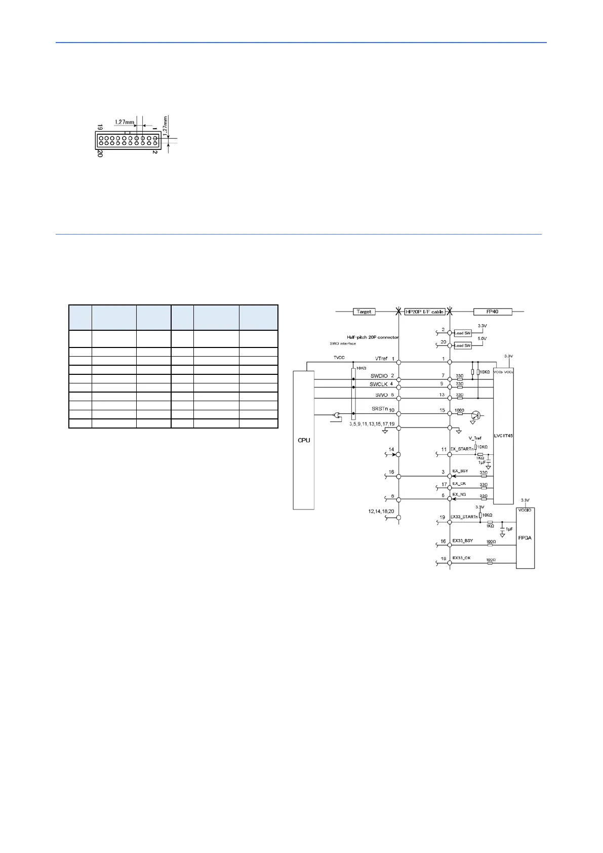
■ 20-pin 1.27mm-pitch connector
Target connector specifications
(Top view on the target board)
Recommended connector
Manufacturer: Samtec, Inc.
Model: FTSH-110-01-L-DV-K
(For detailed dimensions of the connector, refer to the documentation by manufacturer of the
connector.)
*Please refer the pin configuration diagram above and make sure that the connector is in the right direction
before connecting.
Please check the pin number in the signal table above and make sure the signal and the pin numbers
This connector does not support the power supply function to the target.
③ SWD interface
The signal table and target connection reference diagram when connecting a 20-pin 1.27mm pitch connector with SWD
interface are shown below.
Pin
No.
Signal
Output
*1
Pin
No.
Signal
Input/
Output
*1
1 VTref
*2
Output 2 SWDIO
: Input/output is denoted for the target system.
: Connect the I/O power supply of the CPU to VTref.
: Unused. NC.
: Connect the reset signal to the connected CPU with a wired
OR circuit or an OR circuit. The SRSTn signal is an open
collector output.
: In some target systems, this pin may be assigned as a power
supply pin. This product is GND, so do not connect it to the
power line (or leave it unconnected).
: Intended for protection against erroneous insertion.
Target connection reference diagram
To prevent malfunction, the length of wirings from the CPU to the target connector should be kept as short as possible.
If the waveform disturbance exceeds the device specifications, suppress the disturbance by inserting a damping resistor into the signal line or use
other means.