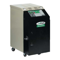
UGH025-0504 Thermolator TW Series
INSTALLATION 3-3
The Thermolator is easy to install, if you plan the location and
prepare the area properly.
Position the Thermolator as close to the
process machine as possible.
Make sure the installation area provides:
r A three-phase power source supplying the correct
current for your Thermolator model. Check the serial tag
on the side of the electrical enclosure for the required
voltage, phase, frequency, full load amps, disconnect fuse
size and minimum wire connection size. Field wiring
should be completed by qualified personnel to the planned
location for the Thermolator. All electrical wiring should
comply with your region’s electrical codes.
r A clean, well-ventilated environment.
The room temperature should not exceed 120°F (48°C)
with 95% non-condensing humidity and should not fall
below 32°F (0°C).
r Minimum clearance for safe operation and main-
tenance. The diagram at right shows minimum clear-
ance for operation. You also need enough clearance in
the rear for water hookups. For maintenance, you
should move the Thermolator to provide at least 36 inches
on any side of the Thermolator.
r A source of water for cooling.
City, tower or chiller water may be used. The minimum
supply pressure is 25 psi and the maximum pressure is
shown in the following chart.
Install plumbing for process and cooling lines.
You will need two 1
1
/
4
-inch NPT male fittings for the
process inlet and outlet and two 3/4-inch NPT male fit-
tings for the cooling inlet and outlet. Larger line sizes are
acceptable as long as they are reduced at the Thermolator
connections. Smaller line sizes are not recommended.
PREPARING FOR
INSTALLATION
1
 Loading...