UGH025-0504 Thermolator TW Series
TROUBLESHOOTING 6-25
Every Thermolator has a solenoid valve assembly that con-
trols the cooling water out flow. Closed circuit (CC) units also
have a vent valve assembly. Solenoid valves also are found on
the optional purge valve.
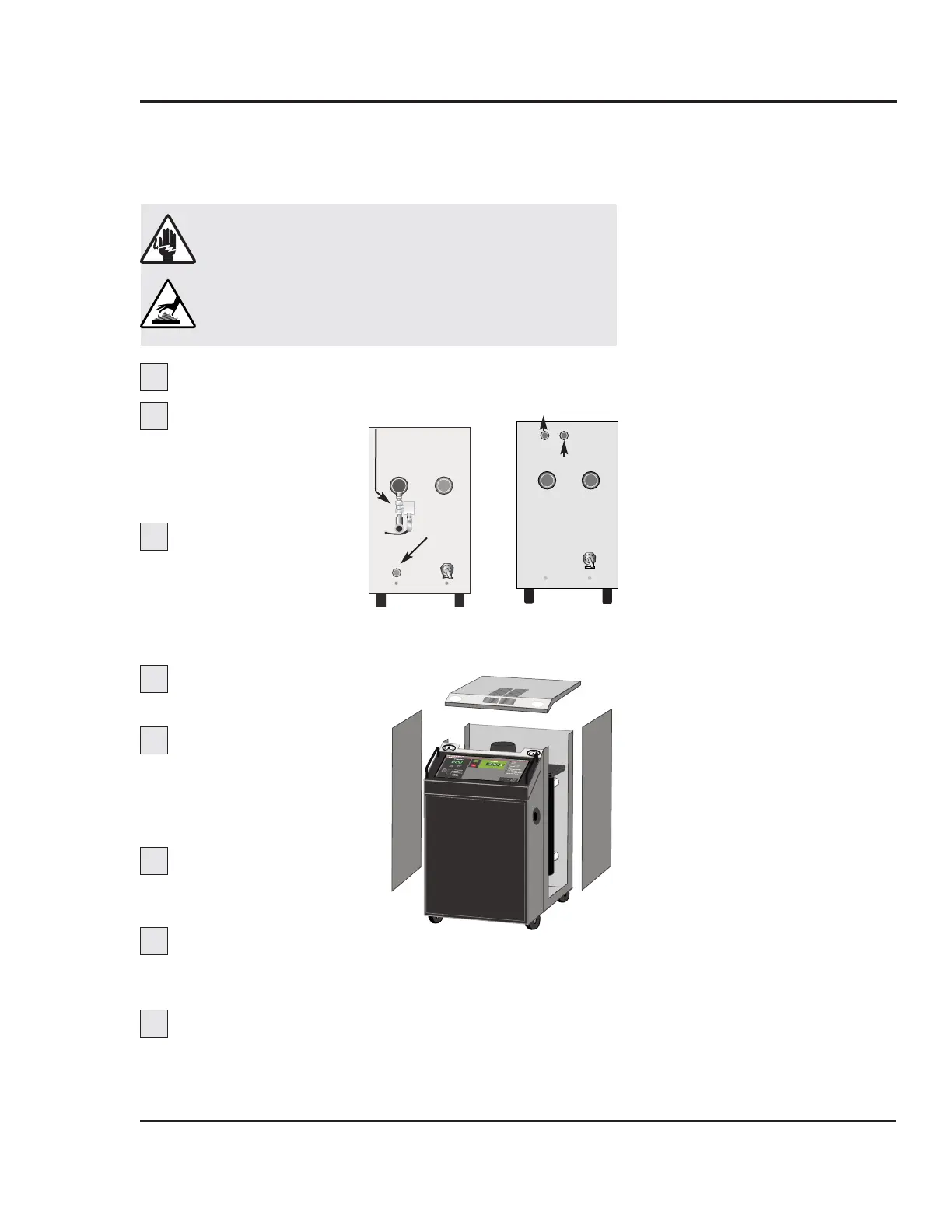
Shut off the cooling water infeed.
Drain the unit of
all
water through the relief
valve port in the rear of
the unit. Use a 1/4 inch
allen key.
Remove the cooling
water out feed. For
closed and isolated cir-
cuit models, also
remove the cooling
water in feed.
Disconnect and lock
out main power.
Remove the top and
side panels of the
Thermolator. Lift the top
panel straight up, then lift
the side panels up.
Remove the cooling
valve from the cooling
water out line.
Disassemble the cooling valve.
See Repairing Solenoid Valves and Repairing Motorized
Valves, Section 6.
Inspect and clean or repair the valve body
assembly. Remove foreign particles and replace damaged
parts as necessary.
Cooling
water in
1
3
WARNING: Electrical shock and
hot surface hazards
Before attempting maintenance of any kind
on the Thermolator, you must stop the unit;
disconnect and lockout the main power supply;
and allow the unit to cool to 100°F (38°C)
DIRECT INJECTION
CLOSED CIRCUIT
ISOLATED CIRCUIT
Cooling
water out
Cooling water out
Cooling water in
6
7
8
2
4
5
REPAIRING
COOLING
VALVES
 Loading...