UGH025-0504 Thermolator TW Series
INSTALLATION 3-11
TW-1, TW-2
C
ONTROL
INITIAL SETUP
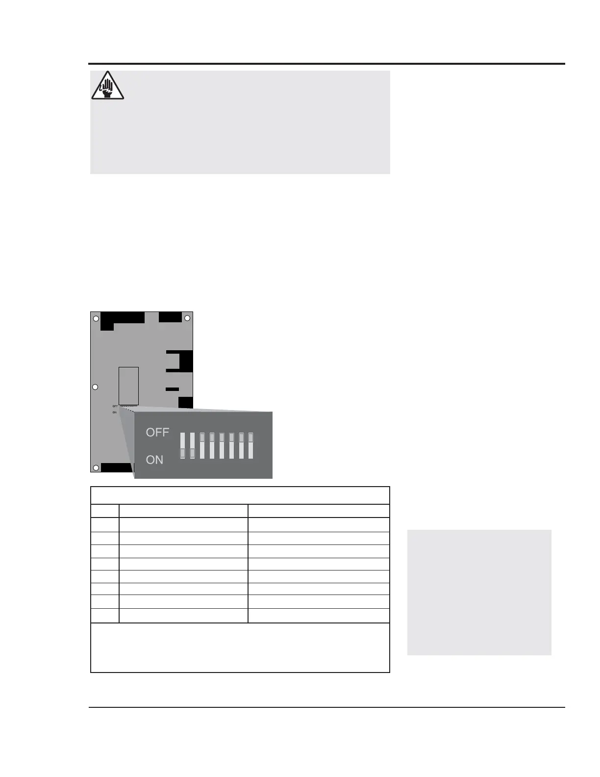
NOTE: All dip switch illustra-
tions in this manual show
switches 7 and 8 set to ON.
If you have an Isolated
Circuit model, these switch-
es should be set to OFF.
Do not change the factory
settings of these dip switch-
es.
The factory-set parameters and operating modes will satisfy
most applications. But you can change some settings and
enable or disable features as needed.
You can modify the parameters for high and low process tem-
perature deviation warnings from the control panel. See
Setting Setpoint Deviation Parameters, Section 3.
Dip switches on the TW-1 and TW-2 motherboard inside the
electrical enclosure allow you to:
r Select the units of measure for tem-
perature displays.
r Enable password protection.
r Enable the Auto Tune.
r Enable the Auto Start feature.
r Enable the Test Mode.
r Select the source point of tempera-
ture control.
To change the dip switch settings, see the appropriate topic
on the following pages.
Dipswitch Configuration
No. OFF ON
1 Display units in °F Display units °C
2 Auto Tune disabled Auto Tune enabled
3 Passcode protect Password reset/modify
4 * Auto Start disabled Auto Start enabled
5 * Control point protect Control point source select
6 Test Mode disabled Test mode enabled
7
†
Controller type selection Controller type selection
8
†
Controller type selection Controller type selection
* Available only on TW-2 models.
† Switches 7 and 8 must be ON for Direct Injection and Closed Circuit
models. Switches 7 and 8 must be OFF for Isolated Circuit models. Do
not change these settings.
WARNING: Electric shock hazard
This equipment is powered by high voltage. Always
disconnect and lock out the main power source
before opening the unit or the electrical enclosure to
modify factory settings. Failure to disconnect and
lock out the main power source can result in severe
personal injury.
 Loading...