EasyManuals Logo

Conair Thermolator TW-1 User Manual

Conair Thermolator TW-1
116 pages
To Next Page IconTo Next Page
To Previous Page IconTo Previous Page
Page #89 background imageLoading...
Page #89 background image
UGH025-0504 Thermolator TW Series
TROUBLESHOOTING 6-21
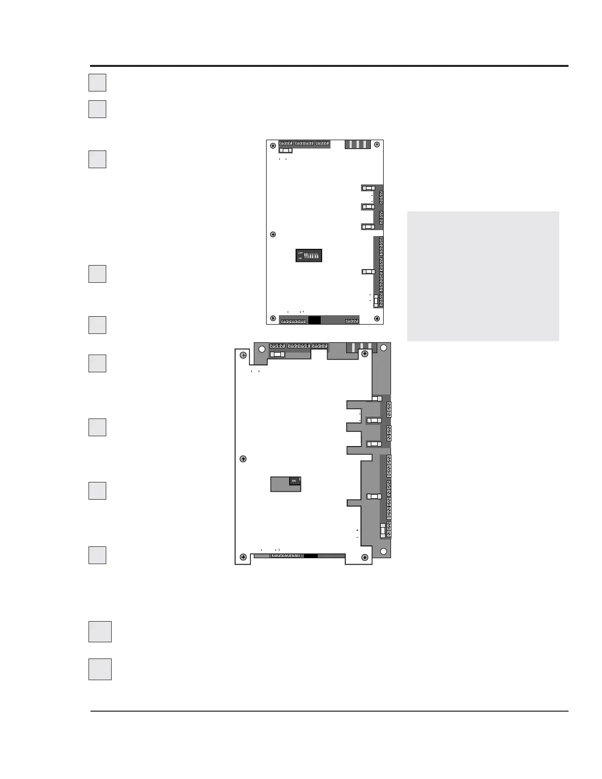
REPLACING THE
MOTHERBOARD
IMPORTANT: Always
refer to the wiring dia-
grams that came with
your Thermolator to
locate specific electrical
components. Illustrations
in the User Guide are
intended to be represen-
tative only.
Disconnect and lockout the main power supply.
Open the electrical enclosure door.
Turn the screw on the front panel counterclockwise to
open.
Mark or label each wire
connected to the motherboard.
The orange shield is labeled
with the connection informa-
tion. You must label the wires
to ensure they are connected to
the correct terminals on the
new motherboard.
Disconnect the wires
from the motherboard by
pulling the terminal blocks up.
Loosen the screws hold-
ing the orange shield.
Remove the mother
board and shield from
the electrical enclosure
as a unit.
Remove the mother
board from the shield
and replace with the
new motherboard.
Reattach the shield
and new motherboard in
the electrical enclosure.
Tighten the screws.
Reconnect the
terminal blocks and
wires to the new board. Make sure you align the terminal
blocks with the correct pins on the board. Push the terminal
blocks onto the pins, taking care not to bend any pins.
Set dip switches 7 and 8 to the correct unit type.
Set ON for DI and CC models; set off for IC models.
Program output monitors on the new board.
See Disabling or Enabling Output Monitors, Section 5.
1
2
3
4
5
6
1 23
45
6
78
CONFIGURATION
DIP SWITCH
OFF
ON
4
3
2
1
4
3
2
1
UNLDR 1/ VENT 2 SOL +
UNLDR 1/ VENT 2 SOL
UNLDR 2/ COOL 1 SOL +
UNLDR 2/ COOL 1 SOL
F5
F4
F2
PUMP
PUMP
PUMP OL
PUMP OL
6
5
4
3
2
1
4
3
2
1
6
5
4
3
2
1
F3
4
3
2
1
F6
PMP AUX
PMP AUX
1FS/ COMP AUX
1FS/ COMP AUX
PUMPDOWN
PUMPDOWN
HEAT/COMP
HEAT/COMP
HTS/COMP OL
HTS/COMP OL
N
C
NC
NO
C
110V
ALARM
LLS/PURGE 3SOL
LLS/PURGE 3SOL +
PURGE 4SOL
PURGE 4 SOL +
3 PHASE INPUT
TCPL'S
SUP RET
AC IN 4
AC IN + 3
AC OUT 2
AC OUT + 1
F1
LLS/WPS
LLS/WPS
AUTOSTART
AUTOSTART
HPS/LPS
HPS/LPS
OPS
OPS
FS TAT
FS TAT
L1
L2
L3
6
5
4
3
2
1
4
3
2
1
Y
R
R
Y
1 2 3 4 5 6 7 8 1 2 3 4
(-2) CONTROL
OPER PNL CABLE
+ 120 Ohm
+ TR
TR
GND
GND
+ TR
TR
120 Ohm
1 23
45
6
78
4
3
2
1
4
3
2
1
6
5
4
3
2
1
4
3
2
1
6
5
4
3
2
1
4
3
2
1
6
5
4
3
2
1
4
3
2
1
1 2 3 4 5 6 7 8 1 2 3 4
CONFIGURATION
DIP SWITCH
OFF
ON
UNLDR 1/ VENT 2 SOL +
UNLDR 1/ VENT 2 SOL
UNLDR 2/ COOL 1 SOL +
UNLDR 2/ COOL 1 SOL
F5
F4
F2
PUMP
PUMP
PUMP OL
PUMP OL
F3
F6
PMP AUX
PMP AUX
1FS/ COMP AUX
1FS/ COMP AUX
PUMPDOWN
PUMPDOWN
HEAT/COMP
HEAT/COMP
HTS/COMP OL
HTS/COMP OL
N
C
NC
NO
C
110V
ALARM
LLS/PURGE 3SOL
LLS/PURGE 3SOL +
PURGE 4SOL
PURGE 4 SOL +
3 PHASE INPUT
TCPL'S
SUP RET
AC IN 4
AC IN + 3
AC OUT 2
AC OUT + 1
F1
LLS/WPS
LLS/WPS
AUTOSTART
AUTOSTART
HPS/LPS
HPS/LPS
OPS
OPS
FSTAT
FSTAT
L1
L2
L3
Y
R
R
Y
(-2) CONTROL
OPER PNL CABLE
+ 120 Ohm
+ TR
TR
GND
GND
+ TR
TR
120 Ohm
7
8
9
10
11

Table of Contents

Questions and Answers:

Question and Answer IconNeed help?

Do you have a question about the Conair Thermolator TW-1 and is the answer not in the manual?

Conair Thermolator TW-1 Specifications

General IconGeneral
BrandConair
ModelThermolator TW-1
CategoryControl Unit
LanguageEnglish

Related product manuals