40 Installation
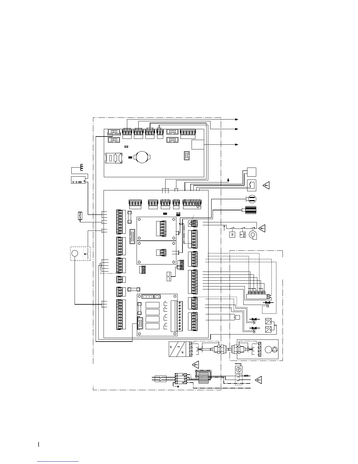
4.6.2 Wiring diagram Condair DL
3V
CR2032
X1X2
J1
RJ45
BAT
SD
X3X4
X19
X5X6
X7
F1 (6.3 AT) F2 (630 mAT)
X9X8 X10
X20
X11 X12
X13X14X15.1X15.2X16
J6
J10
J12
J14
J2
JP5: 10V
JP4: 24V
JP/TR
B7
K1
B6
B5
S2
PE
N/GND
L/24V P
GND
24V P
D–
GND
D+
24V E
GND
GND
24V E
24V 3
GND
GND
GND
24V 1
24V 2
SC2
SC1
A2A1
GND
+
–
GND
+
–
GND
+
–
GND
24V+
J3
H
Error
1 2 3
Service
4 5 6
Running
7 8
Unit On
9 10
+
–
Y
B4
24/10 V
TMP
GND
HUM
24V E
Enable
LinkUp
RS485
BMS
RS485
A3
B2
FQ+
24V P
EN FQ2
EN FQ1
ERR FQ
GND
24V P
5V P
GND
PS4
PS5
J14
J12
J10
J6
RJ45
Etnernet
P<
PS2
Y5
Y6
Y7
Y8
Y9
Y10
Y3
Y1
24V SCB
GND
24V P
24V P
24V SCA
Y2
Y1
Y10
Y9
Y8
Y7
Y6
Y5
PS1
PS2
PS3
LEVEL/T
GND
24V P
U1
PEWVU
321
M1
PEL3L2L1
M
3~
Z
Z
321
PS4 PS5
24V IC
GND
D–
GND
D+
AG+
AG–
Cnd W1
Cnd W2
Tmp W1
Tmp W2
GND
L
L1 N
L1 N
N
PE PE
L
N
F3
Q
SF
S3
Y4
24V P
Y11
Y4
Y3
T1 B1
K2
LS1
LS1-LS4
M2
B3
M
24V E
24V E
24V E
24V E
LEAK
CS1
LVL DP
GND
PE
PE
UV–
UV+
PE
PMP N
PMP L
PE
DOSP–
DOSP+
S1
J7
J4
X18 X17
Legend
A1 Driver board
A2 Control board (CPU) with display
A3 Ag ionisation
B1 Conductivity measuring board
B2 Conductivity sensor
B3 Level sensor disinfection pump (option)
B4 Demand or humidity signal
B5 Ventilaton interlock
B6 High limit humidistat
B7 Air proving switch
F1 Fuse 230V supply
F2 Fuse 10V / 24V supply
F3 Fuse mains supply 10AT
H Remote operating and fault indication board
J1 Cable bridge, if no external enable contact
is connected
J3 Cable bridge, if no monitoring devices are
connected to SC1 and SC2
J4 Jumper for activating the terminating resis-
tor for Modbus network (Jumper must be
connected, if Condair DL is the last unit in
the Modbus network)
J7 Jumper connected: Modbus communication
via RS 485 interface (J6)
JP4 Jumper connected = 24V on X16,
JP5 no jumper!
JP5 Jumper connected = 10V on X16,
JP4 no jumper!
JP/TR Jumper connected to last driver board
K1 External safety chain
Do not apply extraneous voltage with K1
K2 External ushing contact or start
compressed-air ushing (option)
LS1 Control leakage monitoring
LS2-4 Floor sensors for leakage monitoring,
max. 3
M1 Booster pump (Type A only)
M2 Disinfection pump (option)
PS2 Pressure switch (option sterile lter)
PS4 Pressure sensor inlet pressure
PS5 Pressure sensor nozzle pressure
Q Electrical isolator (supplied)
S1 <Humidication On/Off> switch (located on
the front cover of the control unit)
S2 External enable contact humidication
S3 <Control unit On/Off> switch (located on the
bottom plate of the control unit)
SF Snap ferrite for mains supply, lead wires
twice through bore of snap ferrrite
T1 Control board Ag ionisation
U1 Frequency converter (Type A only)
Y1 Safety valve inlet
Y3 Compressed-air ushing valve for
compressed-air ushing (option)
Y4 External water supply ushing valve (option)
Y5-9 Spray valves
Y10 Drain valve
Z ESD cable glands, Expose cable shield here
Control unit
Driver
board
Control
board
Snap ferrite:
Lead wires
twice through
bore of
snap ferrite
High leakage current!
Connect 2x protective
earthing conductor
Do not apply extrane-
ous voltage via K1!
Do not apply extrane-
ous voltage via S2!
Analogue control
or sensor signal
External
voltage supply
10V/24V max. 300 mA
(JP4=24V, JP5= 10V)
Central unit
Abb. 24: Wiring diagram Condair DL