45Installation
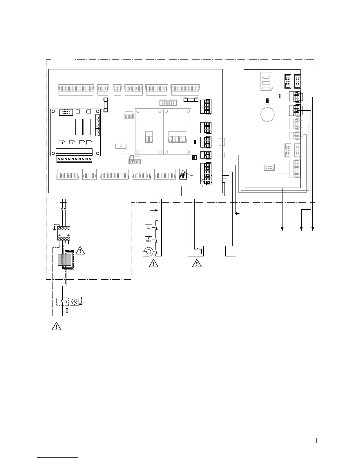
4.6.4 External electrical connections
4.6.4.1 Wiring diagram external electrical connections
B7
K1
B6
B5
S2
+
–
Y
B4
LinkUp
RS485
BMS
RS485
RJ45
Etnernet
3V
CR2032
X1X2
J1
RJ45
BAT
SD
X3X4
X19
X5X6
X7
F1 (6.3 AT) F2 (630 mAT)
X9X8 X10
X20
X11 X12
X13X14X15.1X15.2X16
J6
J10
J12
J14
J2
JP5: 10V
JP4: 24V
JP/TR
PE
N/GND
L/24V P
GND
24V P
D–
GND
D+
24V E
GND
GND
24V E
24V 3
GND
GND
GND
24V 1
24V 2
SC2
SC1
A2A1
GND
+
–
GND
+
–
GND
+
–
GND
24V+
J3
H
Error
1 2 3
Service
4 5 6
Running
7 8
Unit On
9 10
24/10 V
TMP
GND
HUM
24V E
Enable
FQ+
24V P
EN FQ2
EN FQ1
ERR FQ
GND
24V P
5V P
GND
PS4
PS5
J14
J12
J10
J6
24V SCB
GND
24V P
24V P
24V SCA
Y2
Y1
Y10
Y9
Y8
Y7
Y6
Y5
PS1
PS2
PS3
LEVEL/T
GND
24V P
24V IC
GND
D–
GND
D+
AG+
AG–
Cnd W1
Cnd W2
Tmp W1
Tmp W2
GND
24V P
Y11
Y4
Y3
T1 B1
L
L1 N
L1 N
N
PE PE
L
N
F3
Q
SF
S3
24V E
24V E
24V E
24V E
LEAK
CS1
LVL DP
GND
PE
PE
UV–
UV+
PE
PMP N
PMP L
PE
DOSP–
DOSP+
S1
J7
J4
X18 X17
Legend
A1 Driver board
A2 Control board (CPU) with display
B4 Demand or humidity signal
B5 Ventilaton interlock
B6 High limit humidistat
B7 Air proving switch
F1 Fuse 230V supply
F2 Fuse 10V / 24V supply
F3 Fuse mains supply 10AT
H Remote operating and fault indication board
J1 Cable bridge, if no external enable contact is connected
J3 Cable bridge, if no monitoring devices are connected to
SC1 and SC2
J4 Jumper for activating the terminating resistor for Modbus
network (Jumper must be connected, if Condair DL is the
last unit in the Modbus network)
Control unit
Driver
board
Control
board
Snap ferrite:
Lead wires twice through
bore of snap ferrite
High leakage current!
Connect 2x protective
earthing conductor
Do not apply extraneous
voltage via K1!
Do not apply extraneous
voltage via S2!
Analogue control
or sensor signal
External
voltage supply
10V/24V max. 300 mA
(JP4=24V, JP5= 10V)
J7 Jumper connected: Modbus communication via RS 485
interface (J6)
JP4 Jumper connected = 24V on X16, JP5 no jumper!
JP5 Jumper connected = 10V on X16, JP4 no jumper!
JP/TR Jumper connected to last driver board
K1 External safety chain
Do not apply extraneous voltage with K1
Q Electrical isolator (supplied)
S1 <Humidication On/Off> switch (located on the front
cover of the control unit)
S2 External enable contact humidication
Abb. 26: Wiring diagram external electrical connections