36 Installation
4.5 Water installation
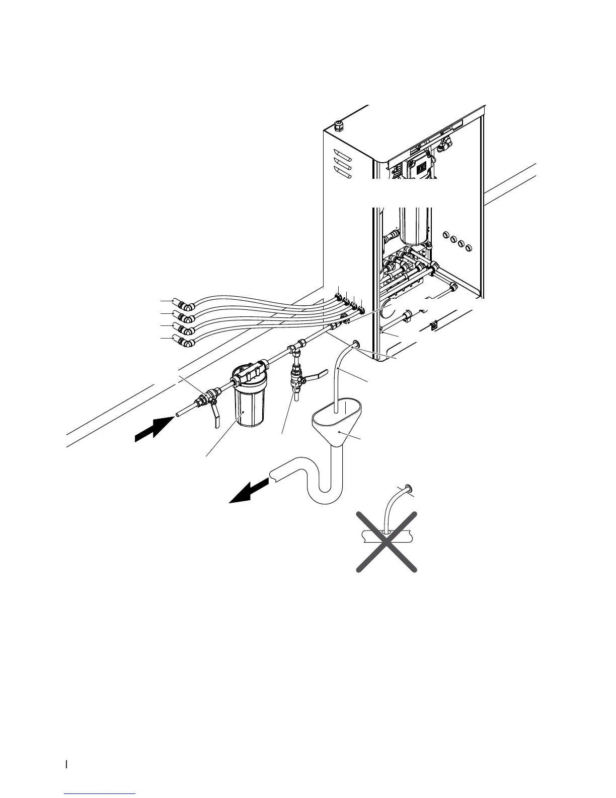
4.5.1 Overview water installation
Abb. 23: Overview water installation
** for hygiene reasons it is not
allowed to guide the drain
water hose into a drain pipe
equipped with a bore!
Tundish with
drain trap
Drain hose with constant downslope
(min. 2%) to open tundish **
Water drain hose rubber
(1m, included in the delivery)
Hose clip water drain hose
RO water connector 12 mm or G 1/2"
Spray circuit connectors
ø10 mm arranged on the left or
the right side of the central unit
Central unit
Spray circuit 1 (red )
Spray circuit 2 (blue)
Spray circuit 3 (yellow)
Spray circuit 4 (green)
Spray circuit lines (con-
stant downslope (min. 2%)
to central unit)
Spray circuit connectors on AHU
Spray circuit 4: green
Spray circuit 3: yellow
Spray circuit 2: blue
Spray circuit 1: red
Shut-off valve
(mandatory, by client)
RO water
3...7 bar
max. 45 °C
0.5...15.0 µS/cm
max. 100 cfu/ml
Water lter 0,005 mm
(recommended, by client)
Test valve ame treatable
(recommended, by client)