46 Installation
4.6.4.2 Installation work external connections
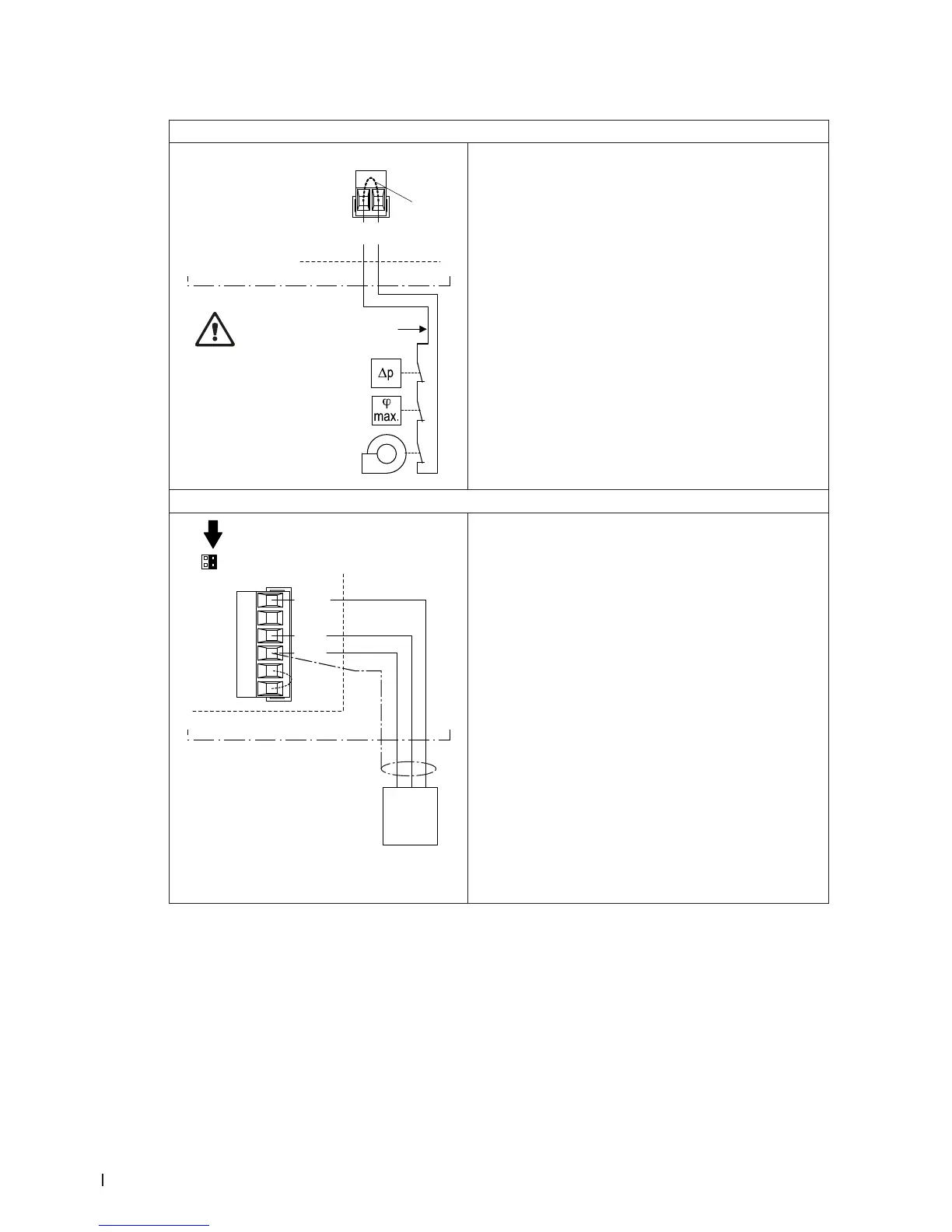
Connecting the external safety chain
X1
B7
K1
B6
B5
SC2
SC1
J3
Control unit
Do not apply extrane-
ous voltage via K1!
The potential-free contacts of external moni t or ing de-
vices (e.g. ventilation interlock, safety high limit humi-
distat, airow monitor, etc.) are connected in series
(safety chain “K1”) to the terminals “SC1” and “SC2” of
the terminal block “X1” on the driver board in accord-
ance with the wiring diagram.
The connecting cable must either be led through the
rectangular cable feed through or a free cable gland
into the control unit.
Note: If, for whatever reason, no external monitoring
devices are connected, a cable bridge “J1” must be in-
stalled on the contacts “SC1” and “SC2” of the terminal
block “X1”.
CAUTION! Do not apply any extraneous voltage to
contacts “SC1” and “SC2” via the contacts of the
external monitoring devices.
Anschluss Anforderungs- oder Feuchtesignal
X16
JP5: 10V
JP4: 24V
24/10V
TMP
GND
HUM
24V E
Enable
Y
B4
–
24V
+
Control unit
The signal cable of an external controller or of a humid-
ity sensor (if the internal P/PI controller is used) are to
be connected according to the wiring diagram to the
terminals “HUM” and GND” of the terminal block “X16”.
The admissible signal values can be found in the techni-
cal data table in the operation manual. The connecting
cable must either be led through the rectangular cable
feed through or a free cable gland into the control unit.
Note: if the external controller or the humidity sensor
shall be supplied with 10 V or 24 V from the driver
board (terminal “24/10V”), the corresponding jumper
(”JP5: 10V” or “JP4: 24V”) must be set and the other
one must be removed.
The shielding of the control signal cable must be con-
nected to terminal “GND”.
Caution! If the shielding of the control signal is already
connected to a po ten tial or a grounded conductor,
do not connect it to terminal “GND”