47Installation
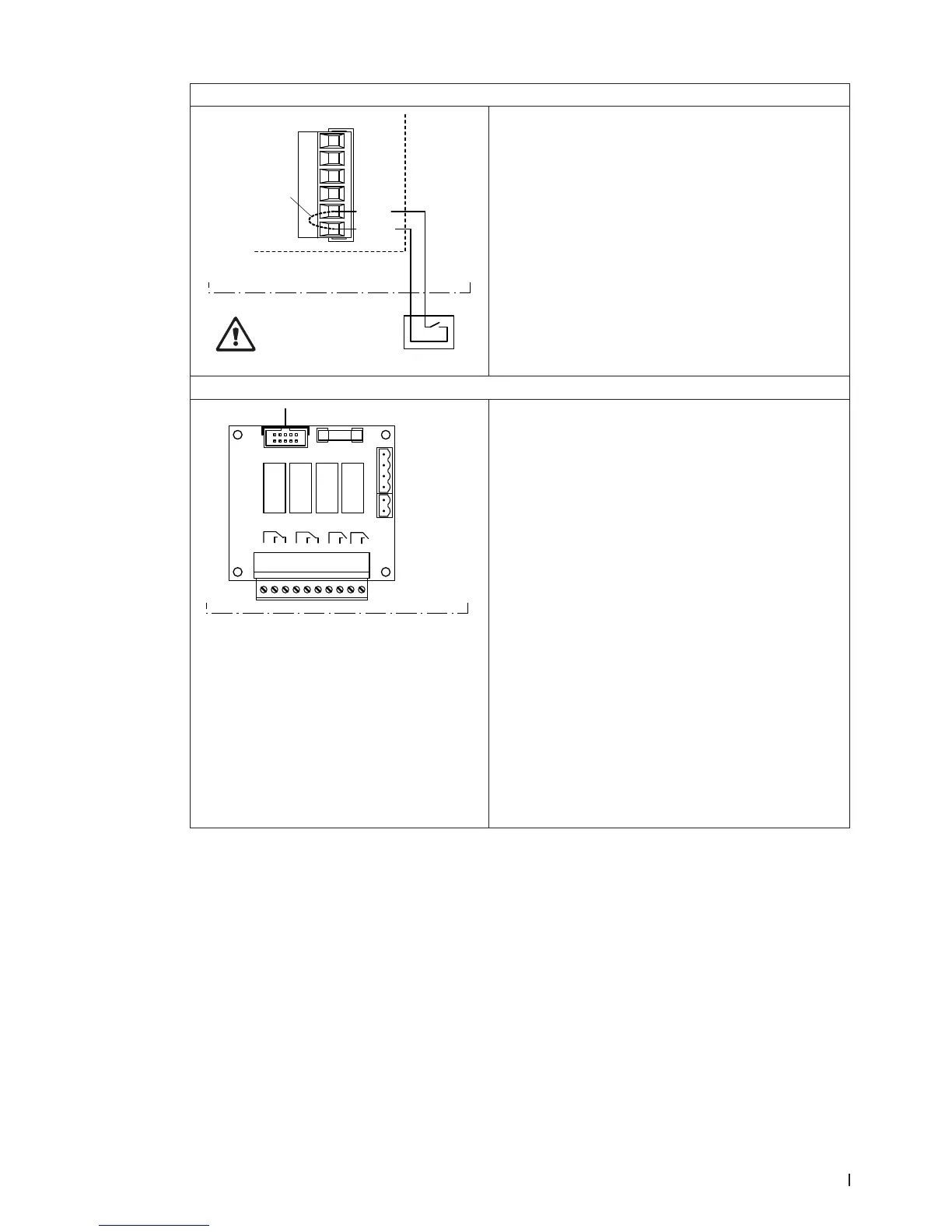
Connecting the external enable switch
X16
J1
S2
24/10V
TMP
GND
HUM
24V E
Enable
Control unit
Do not apply extraneous
voltage via S2!
The potential-free contact of external enable contact is
connected to the terminals “24V” and “Enable” of the
terminal block “X16” on the driver board in accordance
with the wiring diagram.
The connecting cable must either be led through the
rectangular cable feed through or a free cable gland
into the control unit.
CAUTION! Do not apply any extraneous voltage to
terminals via the external enable switch.
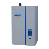
Connecting the remote operating and fault indication
H
Error
1 2 3
Service
4 5 6
Running
7 8
Unit On
9 10
Control unit
The remote operating and fault indication board contains
four potential-free relay contacts for the connection of
the following operating and fault indications:
– “Error”:
This relay is activated if an error is present.
– “Service”:
This relay is activated when the set service interval
has expired.
– “Running”:
This relay closes as soon as the Condair DL hu-
midies.
– “Unit on”:
This relay closes as soon as the voltage supply to
the control unit of the Condair DL is switched on.
The connecting cable must either be led through the
rectangular cable feed through or a free cable gland
into the control unit.
The maximum contact loading is 250V/8A.
Appropriate suppressor modules are to be used for the
switching of relays and miniature contactors.