41Installation
4.6.3 Electrical connections between central unit and control unit
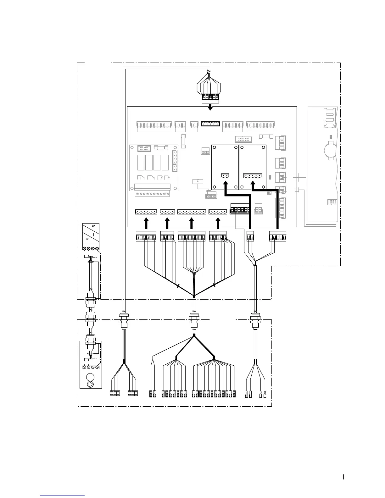
4.6.3.1 Wiring diagram central unit - control unit
grey
white
pink
green
brown
yellow
PS4
PS5
analog
analog
+
-
-
+
U1
PEWVU
321
M1
CH1
MC
PEL3L2L1
M
3~
Z
Z
321
grey
white
pink
yellow
green
brown
Y8 brown / green
Y9 white / yellow
Y7 white / green
Y6 red / blue
Y5 grey / pink
Y10 yellow / brown
Y1 white / grey
Y5 white
Y6 brown
Y7 green
Y8 yellow
Y9 grey
Y10 pink
Y1 blue
Y3 grey / brown
Y4 white / pink
Y4 black
Y3 red
Y5 white
Y5 grey / pink
Y6 brown
Y6 red / blue
Y7 green
Y7 white / green
Y8 brown / green
Y8 yellow
Y10 pink
Y9 grey
Y9 white / yellow
Y10 yellow / brown
Y1 white / grey
Y1 blue
black
Y3 grey / brown
Y3 red
Y4 white / pink
PS2 pink / brown
24VP purple (PS2)
24VP purple
PS2 pink / brown
(Res.) white / blue
X3X4
X10
X6 X5
CH2 CH3
yellow
green
brown
white
brown
white
yellow
green
(Res.) white / blue
Ag+ Lf
Legend
A1 Driver board
A2 Control board (CPU) with display
B1 Conductivity measuring board
CH1 Cable harness pressure sensors
CH2 Cable harness valves and pressure
switch PS2
CH3 Cable harness Ag ionisation and
conductivity sensor
M1 Booster pump (Type A only)
MC Motor connecting cable
T1 Control board Ag ionisation
U1 Frequency converter (Type A only)
Z ESD cable glands, expose cable
shield here
Control unit
Driver
board
Control
board
Central unit
Abb. 25: Wiring diagram central unit - control unit