42 Installation
4.6.3.2 Installation work central unit - control unit
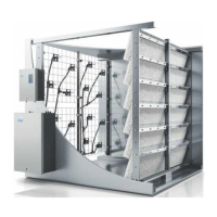
Connecting the motor cable (MC) to the frequency converter (type A only)
U1
PEWVU
321
M1
MC
PEL3L2L1
M
3~
Z
Z
321
Control unit
Central unit
Ex factory the motor cable is connected to the frequency
converter inside control unit. On site the motor cable
must be fed via the cable gland (top left) into the central
unit, and there be connected to the booster pump motor
according to the wiring diagram. At the section where
the motor cable passes through the metallic EMV cable
gland (Z), the cable shield must be exposed to achieve
electrical connection of the cable shield with the EMV
cable gland.
Note: the remaining cable between control and central
unit must be pulled down into the central unit and there
be inserted in a loop into the corresponding cable duct.
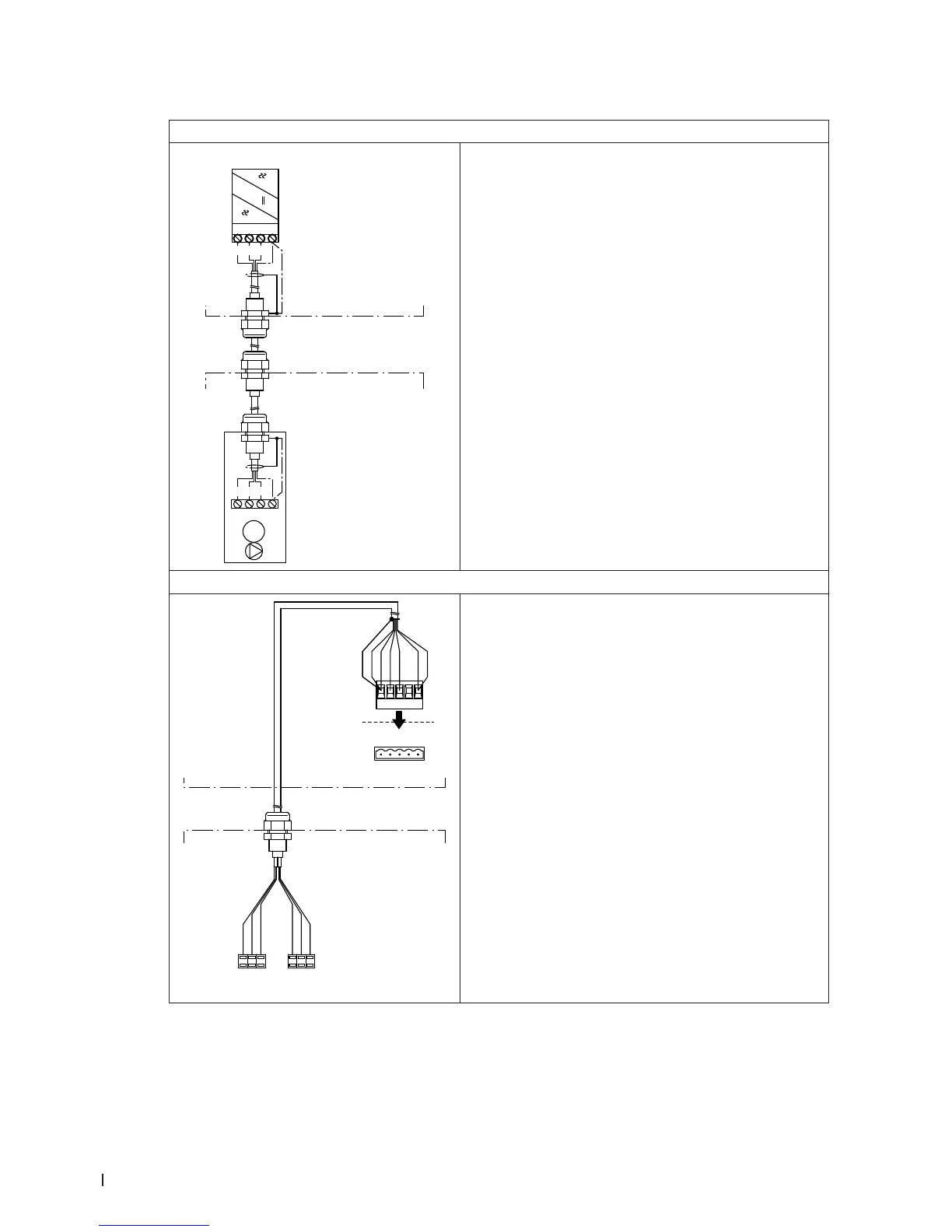
Connecting the cable harness “Pressure sensors” (CH1)
grau
weiss
pink
grün
braun
gelb
PS4
PS5
analog
analog
+
-
-
+
CH1
grau
weiss
pink
gelb
grün
braun
X10
24V P
5V P
GND
PS4
PS5
X10
Control unit
Central unit
Ex factory the cable harness “Pressure sensors” (CH1) is
connected inside central unit to the corresponding pres-
sure sensors. On site the terminal connector of the cable
harness must be connected to the appropriate terminal
(X10) on the driver board inside the control unit.
The cable harness is to be led through the rectangular
cable feed through into the control unit
Note: lead cable harness inside the control unit in the
cable ducts to the corresponding terminal on the driver
board. The remaining cable of the cable harness be-
tween control and central unit must be pulled down into
the central unit and there be inserted in a loop into the
corresponding cable duct.