43Installation
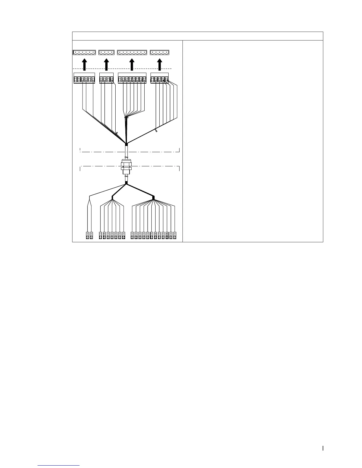
Connecting the cable harness “valves” (CH2)
X3X4X5X6
24V SCB
GND
24V P
24V P
24V SCA
Y2
Y1
Y10
Y9
Y8
Y7
Y6
Y5
PS1
PS2
PS3
LEVEL/T
GND
24V P
24V P
Y11
Y4
Y3
Y8 braun / grün
Y9 weiss / gelb
Y7 weiss / grün
Y6 rot / blau
Y5 grau / pink
Y10 gelb / braun
Y1 weiss / grau
Y5 weiss
Y6 braun
Y7 grün
Y8 gelb
Y9 grau
Y10 pink
Y1 blau
Y3 grau/ braun
Y4 weiss/ pink
Y4 schwarz
Y3 rot
Y5 weiss
Y5 grau / pink
Y6 braun
Y6 rot / blau
Y7 grün
Y7 weiss / grün
Y8 braun / grün
Y8 gelb
Y10 pink
Y9 grau
Y9 weiss / gelb
Y10 gelb / braun
Y1 weiss / grau
Y1 blau
schwarz
Y3 grau / braun
Y3 rot
Y4 weiss / pink
PS2 pink / braun
24VP pupur (PS2)
24VP purpur
PS2 pink / braun
(Res.)weiss / blau
X3X4X6 X5
CH2
(Res.) weiss / blau
Control unit
Central unit
Ex factory the cable harness “valves” (CH2) is connected
inside central unit to the corresponding valves. On site
the terminal connectors of the cable harness must be
connected to the appropriate terminals (X3 to X6) on the
driver board inside the control unit.
The cable harness is to be led through the rectangular
cable feed through into the control unit
Note: lead cable harness inside the control unit in the
cable ducts to the corresponding terminals on the driver
board. The remaining cable of the cable harness between
control and central unit must be pulled down into the
central unit and there be inserted in a loop into the cor-
responding cable duct.