Copyright © 2021 congatec GmbH TCTLm02 30/67
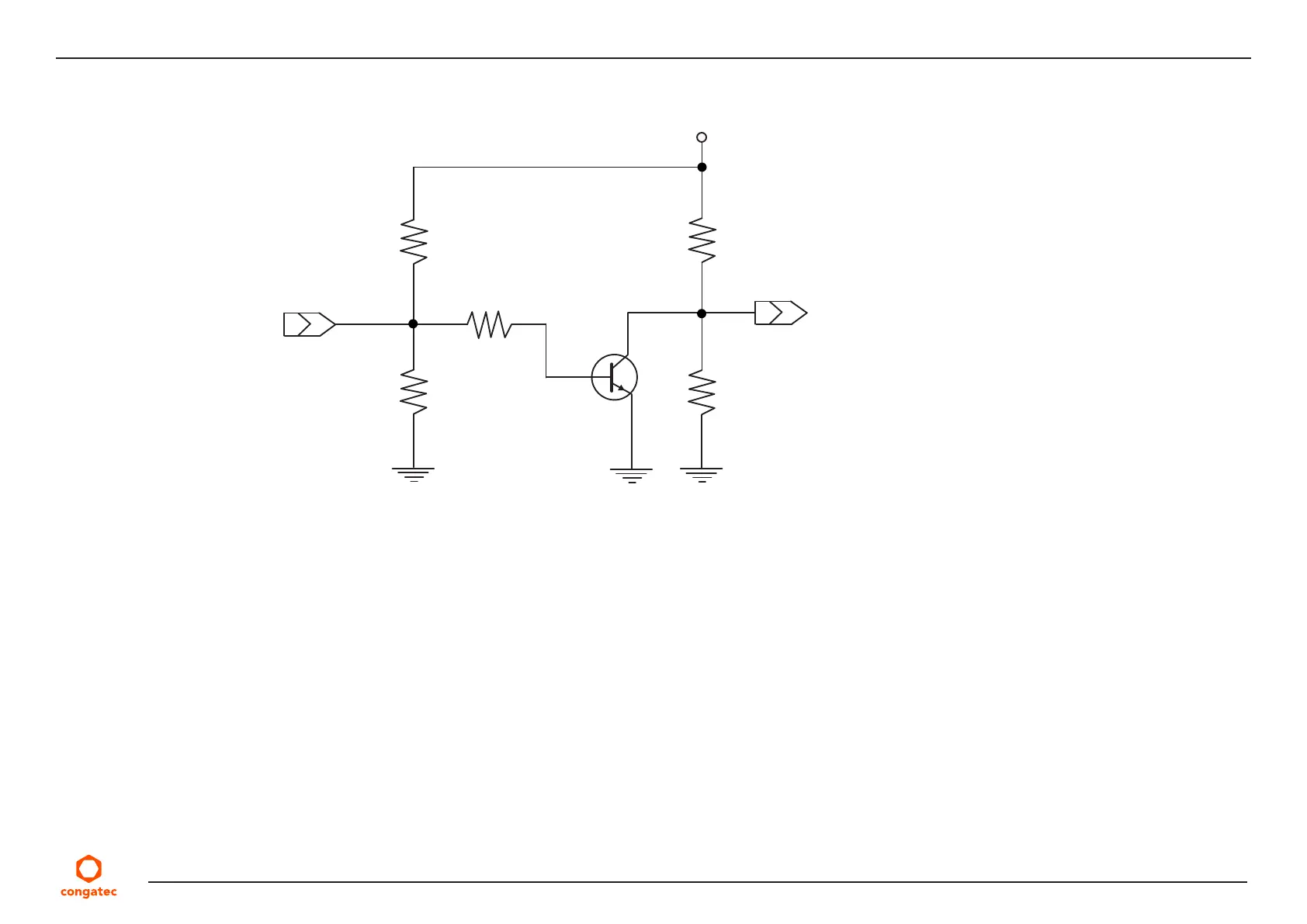
The conga-TC570 PWR_OK input circuitry is implemented as shown below:
The voltage divider ensures that the input complies with 3.3 V CMOS characteristic and also makes it possible to use the module on carrier
board designs that do not drive the PWR_OK signal. Although the PWR_OK input is not mandatory for the onboard power-up sequencing, it
is strongly recommended that the carrier board hardware drives the signal low until it is safe to let the module boot-up.
When considering the above shown voltage divider circuitry and the transistor stage, the voltage measured at the PWR_OK input pin may be
only around 0.8 V when the 12 V is applied to the module. Actively driving PWR_OK high is compliant to the COM Express specification but this
can cause back driving. Therefore, congatec recommends driving the PWR_OK low to keep the module in reset and tri-state PWR_OK when
the carrier board hardware is ready to boot.
The three typical usage scenarios for a carrier board design are:
• Connect PWR_OK to the “power good” signal of an ATX type power supply.
• Connect PWR_OK to the last voltage regulator in the chain on the carrier board.
• Simply pull PWR_OK with a 1k resistor to the carrier board 3.3 V power rail.
With this solution, you must ensure that by the time the 3.3 V is up, all carrier board hardware is fully powered and all clocks are stable.
To Module Power Logic
PWR_OK
R1%4k75S01
TBC847
R1%10kS01
+V12_S
R1%1k00S01
R1%47k5S01
R1%20k0S01