Copyright © 2021 congatec GmbH TCTLm02 64/67
8.2 Bootstrap Signals
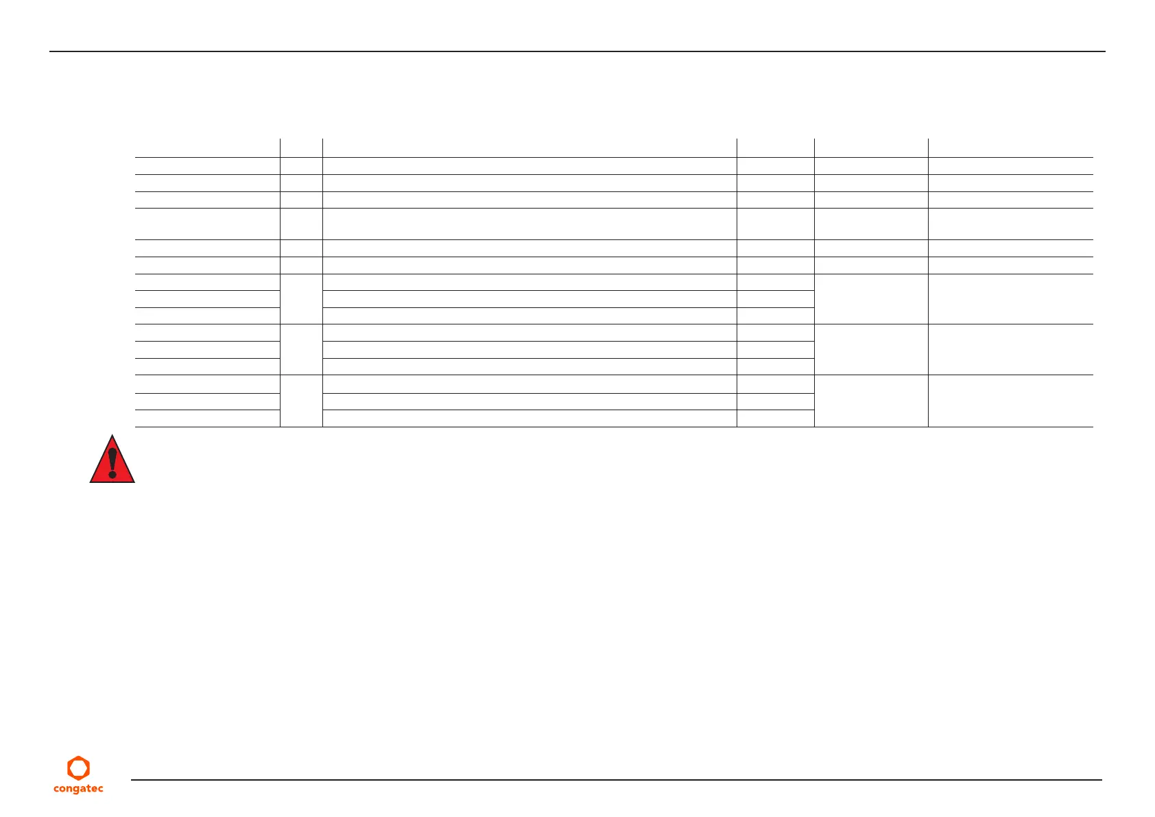
Table 39 Bootstrap Signal Descriptions
Signal Pin # Description of Bootstrap Signal I/O PU/PD Comment
HDA_SDOUT A33 High Definition Audio Serial Data Output O 3.3 VSB
SPKR B32 Output for audio enunciator, the “speaker” in PC-AT systems O 3.3 V
SPI_MOSI A95 Data out from module to carrier board SPI BIOS flash O 3.3 VSB PU 4K75 3.3 VSB
SMB_ALERT# B15 System Management Bus Alert – active low input can be used to generate
an SMI# (System Management Interrupt) or to wake the system.
I 3.3 VSB PU 100 kΩ 3.3 VSB
BIOS_DIS0# A34 Selection strap to determine the BIOS boot device I 3.3 VSB PU 10 kΩ 3.3 VSB
BIOS_DIS1# B88 Selection strap to determine the BIOS boot device I 3.3 VSB PU 10 kΩ 3.3 VSB
DDI1_CTRLDATA_AUX- D16 Multiplexed with DP1_AUX- and HDMI1_CTRLDATA PU 100 kΩ 3.3 V
DP1_AUX- DP AUX- function if DDI1_DDC_AUX_SEL is no connect I/O PCIE
HDMI1_CTRLDATA HDMI/DVI I2C CTRLDATA if DDI1_DDC_AUX_SEL is pulled high I/O OD 3.3 V
DDI2_CTRLDATA_AUX- C33 Multiplexed with DP2_AUX- and HDMI2_CTRLDATA. PU 100 kΩ 3.3 V
DP2_AUX- DP AUX- function if DDI2_DDC_AUX_SEL is no connect I/O PCIE
HDMI2_CTRLDATA HDMI/DVI I2C CTRLDATA if DDI2_DDC_AUX_SEL is pulled high I/O OD 3.3 V
DDI3_CTRLDATA_AUX- C37 Multiplexed with DP3_AUX- and HDMI3_CTRLDATA. PU 100 kΩ 3.3 V
DP3_AUX- DP AUX- function if DDI3_DDC_AUX_SEL is no connect I/O PCIE
HDMI3_CTRLDATA HDMI/DVI I2C CTRLDATA if DDI3_DDC_AUX_SEL is pulled high I/O OD 3.3 V
Caution
1. The signals listed in the table above are used as chipset configuration straps during system reset. In this condition (during reset), they are
inputs that are pulled to the correct state by either COM Express™ internally implemented resistors or chipset internally implemented
resistors that are located on the module.
2. No external DC loads or external pull-up or pull-down resistors should change the configuration of the signals listed in the above table.
External resistors may override the internal strap states and cause the COM Express™ module to malfunction and/or cause irreparable
damage to the module.