Copyright © 2021 congatec GmbH TCTLm02 56/67
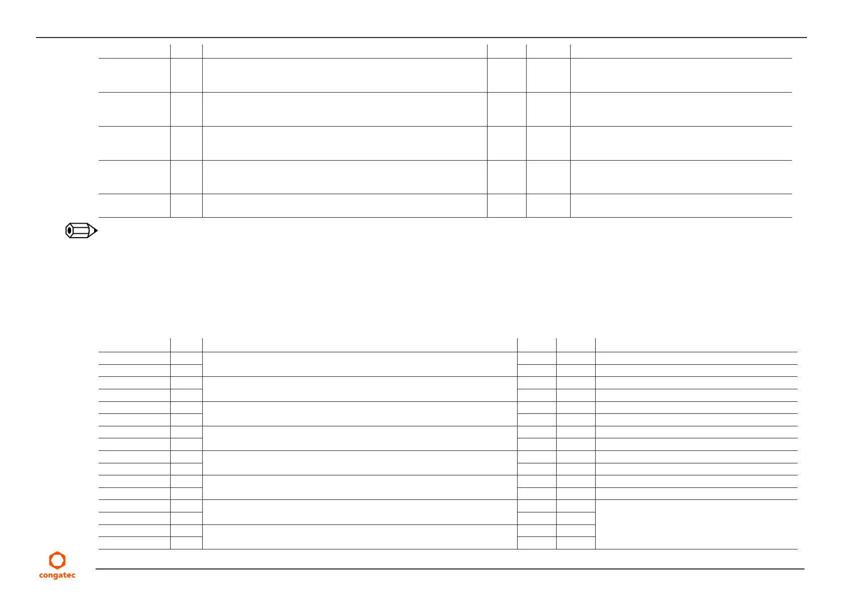
Signal Pin # Description I/O PU/PD Comment
USB_0_1_OC#
1
B44 USB over-current sense, USB ports 0 and 1. A pull-up for this line shall
be present on the module. An open drain driver from a USB current
monitor on the carrier board may drive this line low.
I
3.3 VSB
PU 10 kΩ
3.3 VSB
Do not pull this line high on the carrier board
USB_2_3_OC#
1
A44 USB over-current sense, USB ports 2 and 3. A pull-up for this line shall
be present on the module. An open drain driver from a USB current
monitor on the carrier board may drive this line low. .
I
3.3 VSB
PU 10 kΩ
3.3 VSB
Do not pull this line high on the carrier board
USB_4_5_OC#
1
B38 USB over-current sense, USB ports 4 and 5. A pull-up for this line shall
be present on the module. An open drain driver from a USB current
monitor on the carrier board may drive this line low.
I
3.3 VSB
PU 10 kΩ
3.3 VSB
Do not pull this line high on the carrier board
USB_6_7_OC#
1
A38 USB over-current sense, USB ports 6 and 7. A pull-up for this line shall
be present on the module. An open drain driver from a USB current
monitor on the carrier board may drive this line low.
I
3.3 VSB
PU 10 kΩ
3.3 VSB
Do not pull this line high on the carrier board
USB0_HOST_
PRSNT
B48 Module USB client may detect the presence of a USB host on USB0. A
high values indicates that a host is present.
I
3.3 VSB
PD 1 MΩ Not Supported
Note
1.
These signals have special functionality during the reset process. They may bootstrap some basic important functions of the module. For
more information refer to section 8.2 “Bootstrap Signals”.
Table 25 USB 3.0 Signal Descriptions
Signal Pin # Description I/O PU/PD Comment
USB_SSRX0+ C4 Additional receive signal differential pairs for the Superspeed USB data path I
USB_SSRX0- C3 I
USB_SSTX0+ D4 Additional transmit signal differential pairs for the Superspeed USB data path O
USB_SSTX0- D3 O
USB_SSRX1+ C7 Additional receive signal differential pairs for the Superspeed USB data path I
USB_SSRX1- C6 I
USB_SSTX1+ D7 Additional transmit signal differential pairs for the Superspeed USB data path O
USB_SSTX1- D6 O
USB_SSRX2+ C10 Additional receive signal differential pairs for the Superspeed USB data path I
USB_SSRX2- C9 I
USB_SSTX2+ D10 Additional transmit signal differential pairs for the Superspeed USB data path O
USB_SSTX2- D9 O
USB_SSRX3+ C13 Additional receive signal differential pairs for the Superspeed USB data path I Shared with PCIe lane 7 and configurable via the
BIOS setup menu
USB_SSRX3- C12 I
USB_SSTX3+ D13 Additional transmit signal differential pairs for the Superspeed USB data path O
USB_SSTX3- D12 O