Copyright © 2021 congatec GmbH TCTLm02 41/67
8 Signal Descriptions and Pinout Tables
The following section describes the signals found on COM Express™ Type 6 connectors used for congatec GmbH modules. The pinout of the
modules complies with COM Express Type 6, rev. 3.0.
The table below describes the terminology used in this section. The PU/PD column indicates if a pull-up or pull-down resistor has been used.
If the field entry area in this column for the signal is empty, then no pull-up or pull-down resistor has been implemented by congatec. The “#”
symbol at the end of the signal name indicates that the active or asserted state occurs when the signal is at a low voltage level. When “#” is
not present, the signal is asserted when at a high voltage level.
Note
The Signal Description tables do not list internal pull-ups or pull-downs implemented by the chip vendors, only pull-ups or pull-downs
implemented by congatec are listed. For information about the internal pull-ups or pull-downs implemented by the chip vendors, refer to
the respective chip’s datasheet.
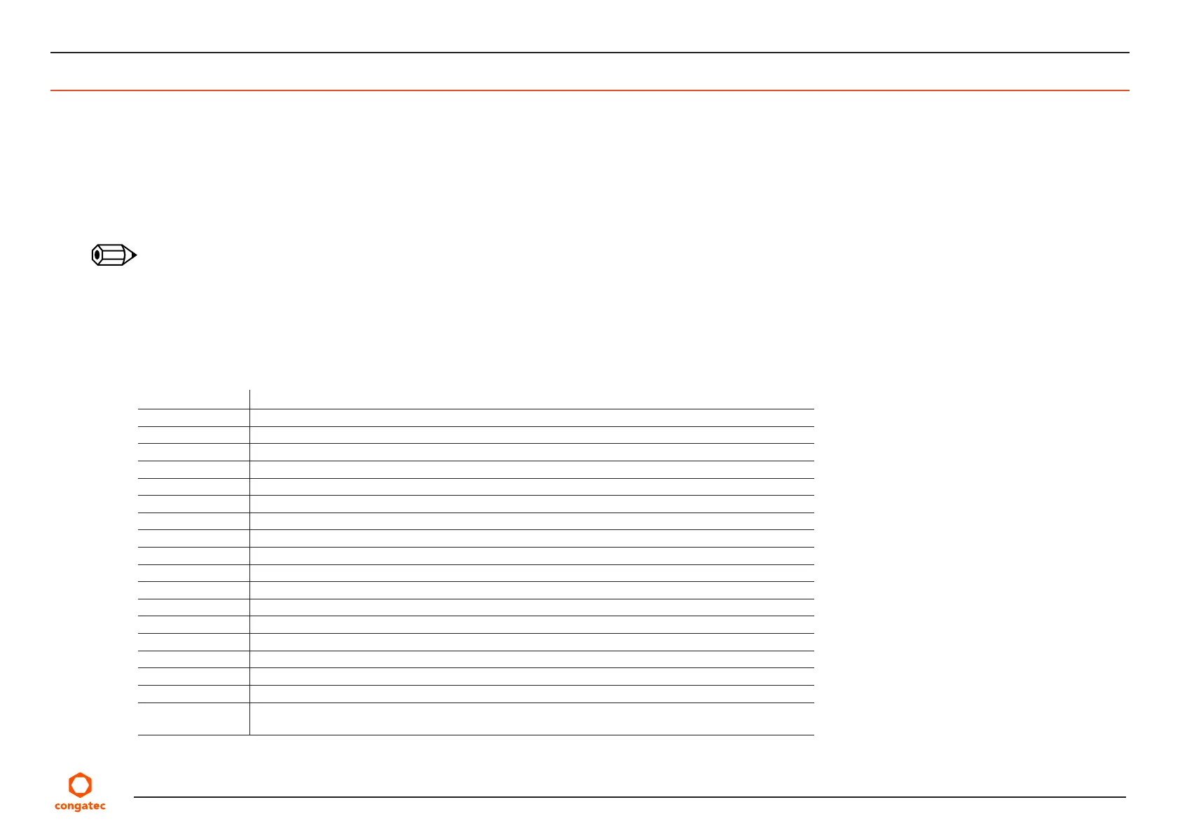
Table 12 Signal Tables Terminology Descriptions
Term Description
PU congatec implemented pull-up resistor
PD congatec implemented pull-down resistor
I/O 3.3V Bi-directional signal 3.3V tolerant
I/O 5V Bi-directional signal 5V tolerant
I 3.3V Input 3.3V tolerant
I 5V Input 5V tolerant
I/O 3.3VSB Input or output 3.3V tolerant active in standby state
O 3.3V Output 3.3V signal level
O 5V Output 5V signal level
OD Open drain output
P Power Input/Output
DDC Display Data Channel
PCIE PCI Express compatible differential signal. In compliance with PCI Express Specification.
PEG PCI Express Graphics
SATA In compliance with Serial ATA specification Revision 2.6 and 3.0.
LVDS Low Voltage Differential Signal - 330 mV nominal; 450 mV maximum differential signal
REF Reference voltage output. May be sourced from a module power plane.
PDS Pull-down strap. A module output pin that is either tied to GND or is not connected. Used to signal
module capabilities (pinout type) to the Carrier Board.