Copyright © 2021 congatec GmbH TCTLm02 58/67
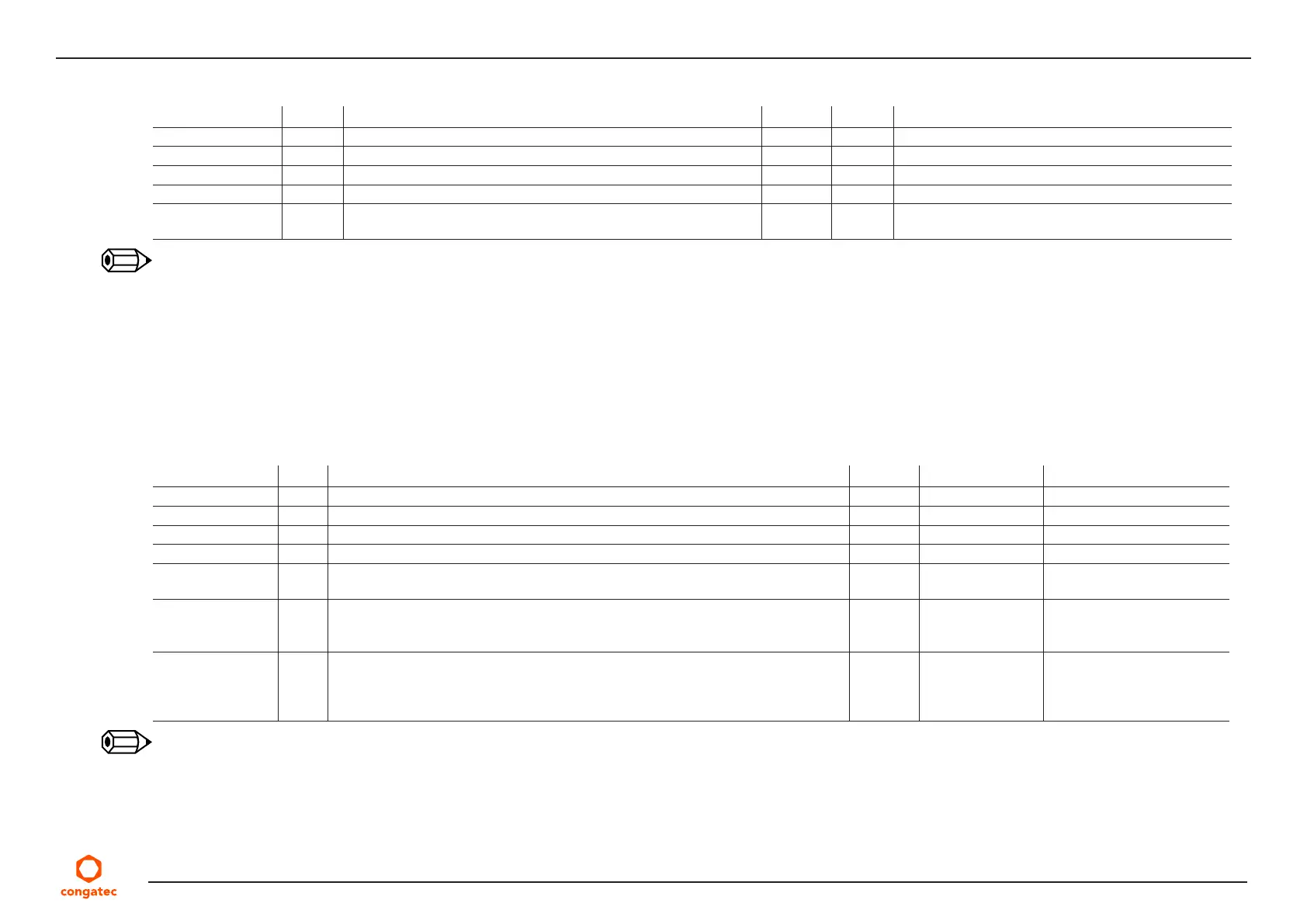
Table 27 High Definition Audio Link Signals Descriptions
Signal Pin # Description I/O PU/PD Comment
HDA_RST#
2
A30 Reset output to codec; active low O 3.3 V
HDA_SYNC
2
A29 Sample-synchronization signal to the codec(s) O 3.3 V
HDA_BITCLK
2
A32 Serial data clock generated by the external codec(s) O 3.3 V
HDA_SDOUT
1, 2
A33 Serial TDM data output to the codec O 3.3 V Bootstrap signal (see note below)
HDA_SDIN[1:0]
1
B29-B30 Serial TDM data inputs from up to three codecs I 3.3 V Bootstrap signal (see note below)
HDA_SDIN2 (pin B28) is not connected
Note
1.
This signal has special functionality during the reset process. It may bootstrap some basic important functions of the module. For more
information refer to section 8.2 “Bootstrap Signals”.
2.
AC’97 codecs are not supported.
Table 28 LPC Signal Descriptions
Signal Pin # Description I/O PU/PD Comment
LPC_AD[0:3] B4-B7 LPC Mode: LPC multiplexed address, command and data bus I/O 3.3 V PU 20 KΩ 3.3 V
LPC_FRAME# B3 LPC Mode: LPC Frame indicates the start of a LPC cycle. O 3.3 V
LPC_CLK B10 LPC Mode: LPC clock output, 33MHz O 3.3 V
LPC_DRQ[0:1]# B8 LPC Mode: LPC serial DMA request I 3.3 V PU 10 KΩ 3.3 V
LPC_SERIRQ A50 LPC Mode: LPC serial interrupt I/O 3.3 V PU 10 KΩ 3.3 V
SUS_STAT# B18 LPC Mode: Indicates imminent suspend operation. It is used to notify LPC
devices that a low power state will be entered soon. LPC devices may need to
preserve memory or isolate outputs during the low power state.
O 3.3 V
ESPI_EN#
1,
B47 This signal is used by the carrier to indicate the operating mode of the LPC/eSPI
bus. If left unconnected on the carrier, LPC mode (default) is selected. If pulled to
GND on the carrier, eSPI mode is selected. This signal is pulled to a logic high on
the module through a resistor. The carrier should only float this line or pull it low.
I Not connected
Note
1.
The conga-TC570 does not support ESPI mode.