4-12
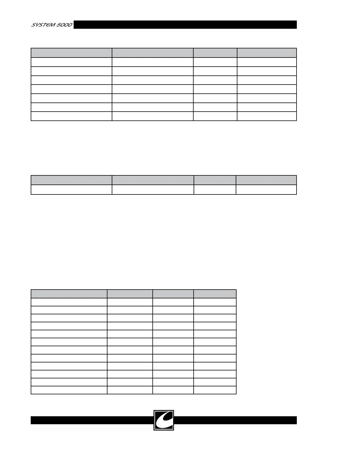
Table 4.5 Allowable RF Leakage Current - Inactive Monopolar Outputs
MEASURED TERMINAL ACTIVATED ACCESSORY MODE RF LEAKAGE (Ma)
Footswitched Active Left Hand Controlled Standard Coag <50
Footswitched Active Right Hand Controlled Standard Coag <50
Footswitched Active Bipolar Footswitch Bipolar Macro <20
Left Hand Controlled Active Right Hand Controlled Standard Coag <50
Left Hand Controlled Active Bipolar Footswitch Bipolar Macro <20
Right Hand Controlled Active Bipolar Footswitch Bipolar Macro <40
Bipolar Left Right Hand Controlled Standard Coag <48
Finally, RF leakage should be measured between
the inactive bipolar outputs while a monopolar
accessory is activated. Do the following:
1) Set the unit for full power for the bipolar
mode noted in Table 4.6. Connect ESU tester
according to manufacturer’s instructions -OR-
the 200-ohm non-inductive resistor in series
with the 250 mA RF ammeter between the
two bipolar output connections.
2) Activate and verify the limit in Table 4.6.
Table 4.6 Allowable RF Leakage Current - Inactive Bipolar Outputs
MEASURED TERMINAL ACTIVATED ACCESSORY MODE RF LEAKAGE (Ma)
Bipolar Right to Left Right Hand Controlled Standard Coag <48
4.6.5 Line Frequency Leakage
CAUTION: To prevent RF current from destroy-
ing the test equipment and/or affecting leakage
readings, set all power settings to zero.
Circuit ground and the Neutral (Low MAINS)
must be connected together for UUT MAINS
leakage testing.
WARNING: Electrocution Hazard. DO NOT
DISCONNECT circuit ground from Earth
Ground unless an isolated MAINS power sup-
ply is used.
Equipment:
These tests are performed most conveniently using
any good quality biomedical electrical safety tester.
Procedure:
1) Connect the electrical safety analyzer to make
the measurements indicated in Table 4.7.
2) Mode: Measure leakage for Bipolar to Neutral
and Chassis to Neutral.
Table 4.7 Line Frequency Allowable Leakage - Inactive
RF output to Neutral LINE GND LIMIT max
Equipotential Ground Normal Closed 30 μA
Equipotential Ground Reversed Closed 30 μA
Equipotential Ground Normal Open 270 μA
Equipotential Ground Reversed Open 270 μA
Dispersive Electrode Normal Closed 15 μA
Dispersive Electrode Reversed Closed 15 μA
Dispersive Electrode Normal Open 15 μA
Dispersive Electrode Reversed Open 15 μA
Bipolar Output* Normal Closed 15 μA
Bipolar Output* Reversed Closed 15 μA
Bipolar Output* Normal Open 15 μA
Bipolar Output* Reversed Open 15 μA
*Measure the Bipolar Output with Bipolar connections shorted together.