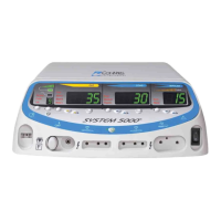
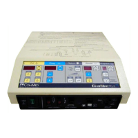
4-20
4.10 DACview
DACview is a troubleshooting aid that allows
access to internal readings. The feature allows
output voltage, current and power that the system
reads to be output to a DVM or oscilloscope.
To use DACview, the system must be in the Test
Mode.
1) Set the system for operation in Test Mode as
described in the preceding section.
2) Connect a DVM to the Control Board test
points labeled TP7 – DAC_VIEW and TP6
– AGND.
3) Turn the power on and press the PC key until
the Test Tones begin.
4) Move the DACview switch (S2 position 8
– the change is recognized, not whether the
switch is on or off).
5) The Monopolar Cut Power Digital Display is
used to display the selected DACview chan-
nel. Since power was just initialized, the
Monopolar Cut Power Digital Display will
display “0” at this point. Select the desired
channel using the Monopolar Cut Power
Adjustment Keys.
6) Move the DACview switch (again, the change
is recognized, not whether the switch is on or
off). The cut power setting will be displayed.
7) To select a different location to monitor with
a DVM, simply move the DACview switch
and the memory locations will be displayed
instead of the cut power. Select the desired
selection and then move the DACview switch
again.
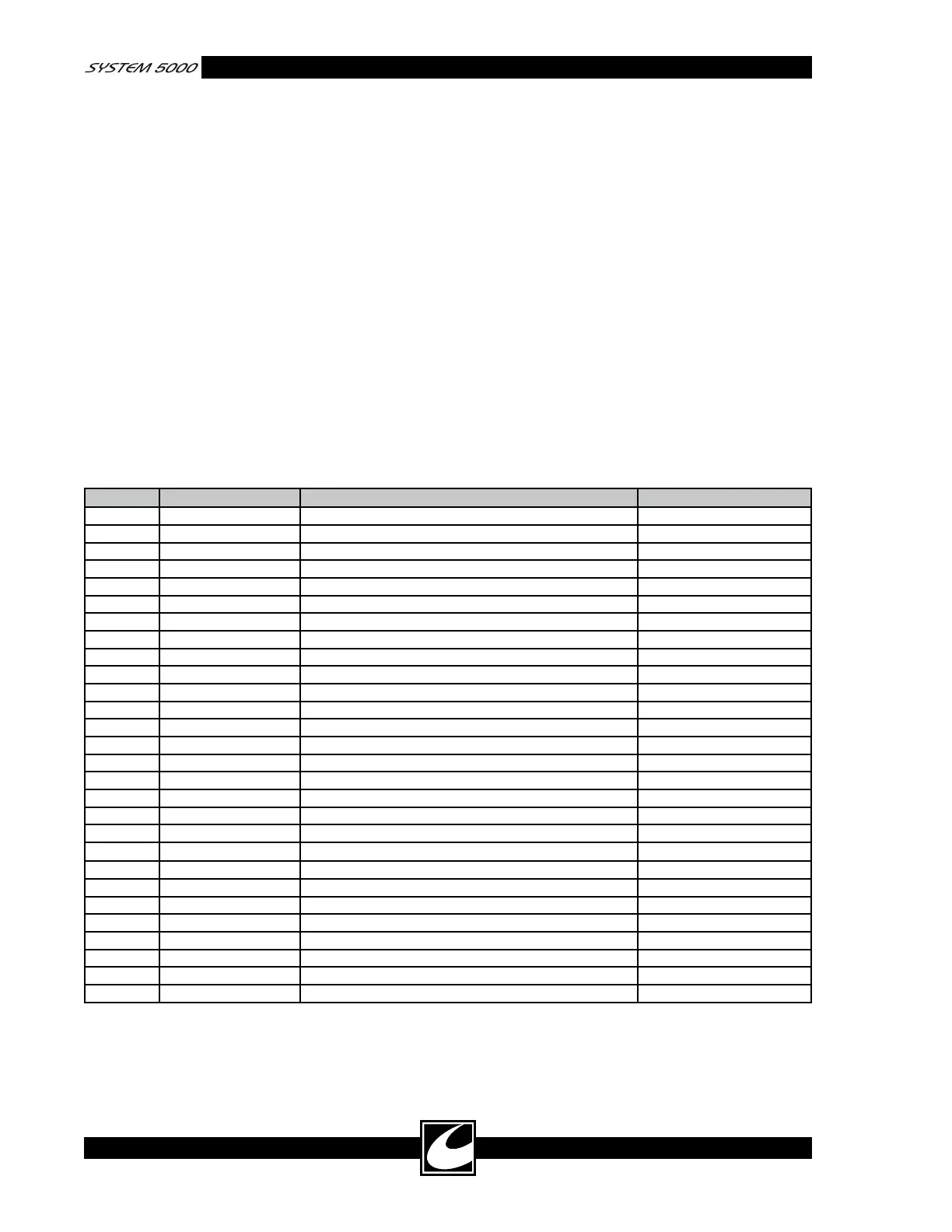
Table 4.10 DACview Channels
Channel Source Function Scaling
0 No channel selected
1 Monitor RF RMS Power (300mS running average) 0.01 V / 1 W
2 Monitor RF RMS Power 0.01 V / 1 W
3 Monitor RF RMS Current 1 V / 1 A
4 Monitor RF RMS Voltage 0.001 V / 1 V
5 Monitor RF RMS Current (300mS running average) 1 V / 1 A
6 Monitor RF RMS Voltage (300mS running average) 0.001 V / 1 V
7 Monitor Max RMS RF Voltage during single activation 0.001 V / 1 V
8 Monitor Reserved- Future Use
9 Monitor H1 accessory, RMS current output 1 V / 1 A
10 Monitor H2 accessory, RMS current output 1 V / 1 A
11 Monitor FT accessory, RMS current output 1 V / 1 A
12 Monitor BP accessory, RMS current output 1 V / 1 A
13 Monitor +HV, High Voltage power supply output 0.01 V / 1 V
14 Monitor Max Power during single activation 0.01 V / 1 W
15 Monitor Max RMS Current during single activation 1 V / 1 A
16 Monitor Calculated output resistance 0.001 V / 1 OHM
17 Monitor A/D Input DC voltage offset 1 V / 1 V
18 Monitor Reserved- Future Use
19 System Controller A.R.M.
TM
resistance 0.01 V / 1 OHM
20 Controller Gate pulse width Variable
21 Controller Output RMS Voltage Variable
22 Controller Output RMS Current Variable
23 Controller Output impedance 0.2V/100 OHM
24 Controller Reserved- Future Use
25 Controller Reserved- Future Use
26 Monitor Calibrated POST RF cut mode voltage 0.001 V / 1 V
27 Monitor Calibrated POST RF coag mode voltage 0.001 V / 1 V