Do you have a question about the ConMed ExcaliburPLUS PC and is the answer not in the manual?
Lists U.S. patent numbers and patents pending.
Displays copyright year and CONMED Corporation's address.
Identifies the European authorized representative.
Explains how the manual's revision level is determined.
General warnings and precautions for equipment use.
Precautions for preparing the electrosurgical unit and accessories.
Safety precautions for patient preparation and electrosurgery use.
Cautions for operating the electrosurgical unit safely.
Safety precautions for testing and servicing the unit.
Covers input power, protection, leakage, certifications, accuracy, regulation.
Specifies operating conditions, clearance, and cooling.
Includes RF leakage, pad monitor, audio, power cord, dimensions, modes.
Explains symbols used on the control panel.
Explains symbols used on the output panel.
Explains symbols found on the top cover.
Explains symbols found inside the unit.
Explains symbols used on the rear panel.
Graph showing output power relative to power display setting.
Graph showing peak voltage vs power setting.
Graphs of output power vs load resistance for Pure Cut and Blend 1.
Graphs of output power vs load resistance for Blend 2 and Blend 3.
Graphs of output power vs load resistance for Standard and Spray Coag.
Graphs of output power vs load resistance for Bipolar Coag and Cut.
Instructions for unpacking, inspecting, installing, and preliminary testing.
Overview of unit controls, displays, and connectors.
Details controls and indicators on the front panel.
Describes connectors and controls on the output panel.
Details components and connectors on the rear panel.
Steps for powering up, connecting accessories, and selecting modes.
How to activate the unit and adjust power levels.
How to store and recall up to 9 settings.
Detailed steps for saving mode and power settings.
Instructions for recalling stored settings.
How to enable and use remote power adjustments.
Steps to adjust power using the pencil control.
Covers general info, cleaning, inspection, and testing.
Addresses alarms, fault codes, and contact info.
How to address Return Fault alarms.
Explains ACC and ERR fault codes and their resolution.
Disposal and component material information.
Details AC power conversion, supplies, and transformers.
Explains controller PWB, WDT, POR, I/O, and memory.
Covers base voltage, IFAIL DAC, waveform, tone generators, and monitors.
Discusses software, CAL mode, and calibration procedures.
Describes display, keyboard, and indicators.
Explains power amplifier, RF output, ARM, continuity, and footswitch isolation.
Shows representative power amplifier and signal waveforms.
Covers general info, cleaning, component access.
Annual performance testing procedures.
Covers ground integrity, leakage, and output power tests.
Covers ARM calibration, voltage monitor check, and CAL mode.
Steps to enter the CAL Mode for calibration.
Navigating the CAL Mode menu options.
How to enter and exit modes within CAL Mode.
Understanding calibration status flags.
How calibration values are tested and stored.
Steps for calibrating output power.
Calibrating monopolar output power.
Calibrating bipolar output power.
Calibrating the ARM circuitry.
Explains how fault codes are generated and displayed.
Using dIA 2, dIA 1, and clearing fault codes.
Steps for troubleshooting specific circuit components.
How to mitigate interference issues with other equipment.
Information on ordering parts and schematics.
Lists accessory related fault codes and causes.
Lists error codes related to internal unit failures.
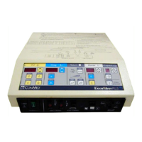
| Category | Electrosurgical Generator |
|---|---|
| Manufacturer | ConMed |
| Modes | Cut, Coagulation, Bipolar |
| Line Voltage | 100-240 VAC |
| Line Frequency | 50/60 Hz |
| Cut Modes | Pure, Blend |
| Bipolar Modes | Standard |
| Output Power (Cut) | 300W |
| Output Power (Coag) | 120W |