EasyManua.ls Logo

ConMed Advantage - User Manual

ConMed Advantage
166 pages
Print Icon
To Next Page IconTo Next Page
Loading...
The Advantage
®
, E9000
®
and PowerPro
®
Systems Instruction Manual
CONTROLLER
OPERATION
A
E9000
®
HANDPIECES
B
MICROCHOICE
®
HANDPIECES
C
SHAVER
HANDPIECES
D
MINI-DRIVER™
HANDPIECES
E
MAINTENANCE
F
TECHNICAL
SPECIFICATIONS
G

Table of Contents

Questions and Answers

  • J
    Jacqueline MitchellAug 7, 2025
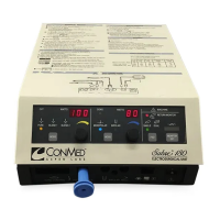
    How to troubleshoot ConMed Medical Equipment controller that does not power on?
    • M
      Matthew HamiltonAug 7, 2025
      If your ConMed Medical Equipment controller doesn't power on, it might be due to a few reasons. First, ensure the power cord is properly plugged in. If it is, check the fuses; a blown fuse can prevent the device from powering on. Replace the fuses if necessary.
  • T
    Tyler SotoAug 12, 2025
    What to do if the ConMed Medical Equipment handpiece does not operate?
    • E
      evelyn49Aug 12, 2025
      If the handpiece on your ConMed Medical Equipment isn't working, there are several potential causes: * Check the handpiece cord to ensure it's securely connected to both the handpiece and the controller receptacle. * If applicable, verify the handpiece safety is in the correct operating position. * If you're using a footswitch, make sure its cord is securely connected to the controller receptacle. If these steps don't resolve the issue, the handpiece cord, button, or the handpiece itself may be faulty and require service or replacement.
  • T
    Tammy FisherAug 18, 2025
    What to do if ConMed Medical Equipment MicroChoice, Group 2 handpiece overheats?
    • K
      Kenneth PetersonAug 19, 2025
      If a MicroChoice, Group 2 handpiece on your ConMed Medical Equipment is overheating, it could be due to moisture in the handpiece. Try resterilizing the handpiece according to the specified sterilization parameters and drying times. Also, worn bearings in the bur guard can cause overheating.
  • T
    tonyahopkinsAug 25, 2025
    Why is there leakage at the tubing handpiece cassette and handpiece interface in ConMed Medical Equipment?
    • E
      Emily MooreAug 25, 2025
      If you're experiencing leakage at the tubing handpiece cassette and handpiece interface of your ConMed Medical Equipment, it may be because the handpiece cassette isn't completely or correctly attached to the handpiece. Remove the tubing handpiece cassette from the handpiece and reinstall it. If the leakage continues, try replacing it with a new tubing set.
  • S
    Stanley BuchananAug 30, 2025
    Why is ConMed Medical Equipment CoolFlex High Speed Drill overheating?
    • D
      david33Aug 31, 2025
      If the CoolFlex High Speed Drill in your ConMed Medical Equipment overheats, it might be because the tubing set isn't completely primed. Prime the tubing set by following the priming procedure.

Summary

1.0 INTRODUCTION

1.1 Intended Use

Defines the purpose and applications of the Advantage, E9000, and PowerPro systems.

1.2 Contraindications

Lists conditions where the Advantage and E9000 systems are not recommended.

1.3 Warnings and Precautions

1.3.1 Warnings

Critical information regarding serious adverse reactions and safety hazards.

1.3.2 Precautions

Instructions for special care to ensure safe and effective use of the equipment.

1.4 Symbol Definitions

Controller Markings

Explains symbols found on the controller interface.

Graphical Display Symbols

Explains symbols used in the controller display.

1.5 Environmental Directives

1.6 System Indicators

1.6.1 Advantage Controller Front Panel (Top Portion)

Identifies and explains components on the Advantage controller's top front panel.

1.6.2 Advantage Controller Front Panel (Bottom Portion)

Identifies and explains components on the Advantage controller's bottom front panel.

1.6.3 Advantage Controller Back Panel

Identifies and explains components on the Advantage controller's back panel.

1.6.4 E9000 Controller Front Panel

Identifies and explains components on the E9000 controller's front panel.

1.6.5 E9000 Controller Back Panel

Identifies and explains components on the E9000 controller's back panel.

1.6.6 PowerPro Controller Front Panel

Identifies and explains components on the PowerPro controller's front panel.

1.6.7 PowerPro Controller Back Panel

Identifies and explains components on the PowerPro controller's back panel.

1.7 Handpieces

1.7.1 GROUP 1 HANDPIECES

Details Group 1 handpieces: Cranial Perforator Drive, High Speed Shaver, CoolFlex Drill.

1.7.2 GROUP 2 HANDPIECES

Details Group 2 handpieces: MicroChoice Drills and Saws, Modular Handpiece.

1.7.3 GROUP 3 HANDPIECES

Details Group 3 shaver handpieces: Basic, 2-Button, and Full-Function types.

1.7.4 GROUP 4 HANDPIECES

Details Group 4 handpieces: Mini-Driver Electric Handpiece.

1.8 Footswitches

1.8.1 Footswitch, 2-Pedal (5020-053) Operation

Explains 2-pedal footswitch operation with various handpieces.

1.8.2 Footswitch, 3-Pedal (C9863) Operation

Explains 3-pedal footswitch operation with various handpieces.

1.8.3 Tubing Sets

Describes various tubing sets, their components, and usage.

2.0 SYSTEM INSTALLATION and OPERATION

2.1 Installation and Setup

Instructions for setting up the system, including power and fluid bag attachment.

2.1.1 Handpiece Cord Installation

Explains how to attach and remove handpiece cords.

2.1.2 Footswitch and Handpiece to Controller Installation

Guides on connecting footswitches and handpieces to the controller.

2.1.2.1 Connecting the Footswitch

Details how to connect the footswitch to the controller.

2.1.2.2 Connecting an APEX Handpiece

Explains connecting APEX handpieces to controllers.

2.1.2.3 Connecting all Group 1 and Group 2 Handpieces

Guides on connecting Group 1 and Group 2 handpieces to controllers.

2.1.2.4 Connecting the Mini-Driver (K500) Handpiece

Explains connecting the Mini-Driver handpiece using an adapter.

2.1.2.5 Connecting a PowerPro Handpiece

Guides on connecting PowerPro handpieces to controllers.

2.1.3 Controller Options;Function Switches and Settings

Explains setting controller options using DIP switches.

2.1.3.1 Controller Options;Function Switch Settings

Details DIP switch functions for E9000/Advantage controllers.

2.1.3.1 Controller Options;Function Switch Settings

Details DIP switch functions for PowerPro/Advantage controllers.

2.1.3.2 Switch 1 - “Day-to-Day” Memory Storage Operation

Explains using Day-to-Day memory storage for handpiece settings.

2.1.3.3 Switch 2 - Footswitch Mode Selection

Explains selecting Variable Speed or ON/OFF footswitch modes.

2.1.3.4 Switch 3 - Audio Selection

Explains turning audio feedback on or off.

2.1.3.6 Switch 4 - Oscillate Mode Selection (Shaver Handpieces Only)

Explains single- or multi-turn oscillate mode for shaver handpieces.

2.1.3.7 Switch 4 - Oscillate Mode Selection (Turbo Shaver Handpieces Only - D9920 and D9924)

Explains oscillate mode selection for Turbo Shaver Handpieces.

2.1.3.8 Switch 5 - Window Indexing

Explains enabling/disabling Window Indexing for shaver handpieces.

2.1.3.9 Switch 5 - Display Mode Selection

Explains selecting Text or Graphics display mode.

2.1.3.10 Switch 6; Switch 7 - Shaver Default Speed Setting

Explains setting default operating speed for shaver handpieces.

2.1.3.12 Switch 7 - Shaver Button Setting

Explains enabling or disabling shaver handpiece buttons.

2.1.4 Tubing Set Cassette Installation

Provides step-by-step instructions for installing the tubing set cassette.

2.1.5 Controller Operation

Guides on operating the controller after settings and tubing are attached.

2.1.6 PowerPro Console Irrigation

Describes Hall Irrigation Pump installation with PowerPro controller.

2.1.6.1 Irrigation Pump Installation

Details the installation of the Hall Irrigation Pump.

2.1.6.2 Irrigation Pump Operation

Explains operating the Hall Irrigation Pump and adjusting flow rates/speeds.

3.0 HANDPIECE OPERATION

3.1 High Speed Shaver (E9005) Operation

Detailed operation instructions for the E9005 High Speed Shaver.

3.2 CoolFlex High Speed Drill (E9010) Operation

Provides operational instructions for the E9010 CoolFlex High Speed Drill.

3.3 Cranial Perforator Drive (E9015) Operation

Describes the operation of the E9015 Cranial Perforator Drive.

3.4 MicroChoice Drills

Details various MicroChoice drills, specifications, and operation.

3.5 MicroChoice Saws

Details various MicroChoice saws, operation, and blade handling.

3.6 MicroChoice Modular Handpiece Attachments

Lists Mini-Driver handpiece attachments and accessories.

3.9 Group 3 Handpiece Operation

General operation instructions for Group 3 shaver handpieces.

3.10 Mini-Driver Handpiece, Attachments and Accessories

Lists Mini-Driver handpiece attachments and accessories.

3.11 Handpiece Default Settings

4.0 MAINTENANCE

4.1 Cleaning and Sterilizing

Provides instructions for cleaning and sterilizing handpieces, controllers, and accessories.

4.2 Troubleshooting

Table of common symptoms, causes, and corrective actions for system issues.

4.3 Calibration

Information on system calibration; noted as factory set.

4.4 Fuse Replacement and Voltage Selection Means

Instructions for replacing fuses and selecting voltage.

4.5 Bur Guard Testing Procedure

Procedure for testing bur guards for worn bearings and overheating.

4.6 Ground Continuity Test

Explains how to perform a ground continuity test.

4.7 Leakage Test

Details how to perform an AC leakage test on the instrument.

5.0 TECHNICAL SPECIFICATIONS

5.1 Theory of Operation

Explains the operating principles of the Advantage, PowerPro, and E9000 systems.

5.2 Controller Specifications

Lists operating requirements and specs for Advantage, E9000, and PowerPro controllers.

5.3 Power Cord Requirements

Details power cord specifications for 100/120 VAC and 220/240 VAC.

5.4 System Environmental Requirements

Specifies operating and storage environmental conditions and EMC compliance.

5.8 Handpieces Specifications

Lists default speeds, torque, length, and weight for various handpieces.

6.0 ACCESSORIES

6.1 Handpieces, Attachments and Accessories List

Detailed list of all handpieces, attachments, and accessories with REF numbers.

7.0 CUSTOMER SERVICE

7.1 Assistance and Repair

Contact information and procedures for product support and repairs.

ConMed Advantage Specifications

General IconGeneral
BrandConMed
ModelAdvantage
CategoryMedical Equipment
LanguageEnglish

Related product manuals