10
•The PowerPro Electric Modular
(PRO2100E) and Two-Trigger
(PRO2200E) handpieces will NOT
operate in Port 2. If these handpieces are
connected to Port 2, “INVALID
HANDPIECE” will display.
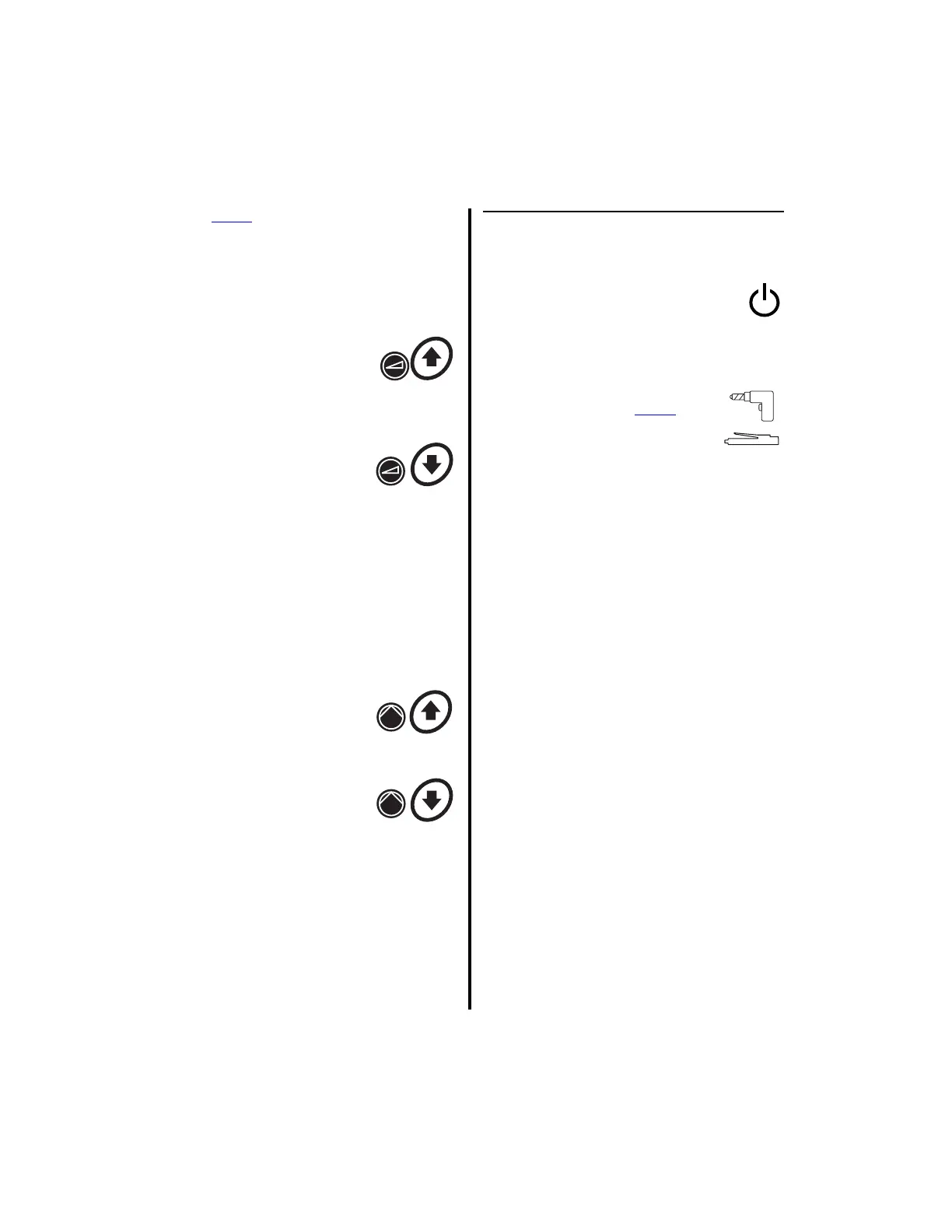
4. Speed Increase Button -
Press to increase the
handpiece speed for
handpieces connected to Port
1 or Port 2.
5. Speed Decrease Button -
Press to decrease the
handpiece speed for
handpieces connected to Port
1 or Port 2.
6. Top Display — Displays handpiece speeds,
irrigation flow rates, instructions, operating
modes and error messages. Displays actual
speed while the handpiece is operating, and
the set speed when the handpiece is
inactive. Flow rate, as a percentage,
displays when the pump is enabled.
7. Flow Increase Button —
Press to increase the pump
flow rate for handpieces
connected to Port 1 or Port 2.
8. Flow Decrease Button —
Press to decrease the pump
flow rate for handpieces
connected to Port 1 or Port 2.
9. Optical Sensor — Senses whether or not a
tubing set is connected.
10. Tubing Cassette Receptacle — Accepts
the various tubing sets. See “6.1
Handpieces, Attachments and
Accessories” on page 149 for a list of
associated tubing sets.
1.6.2 Advantage Controller Front
Panel (Bottom Portion)
11. Standby Power Switch — To
activate the controller, place this
switch to the on position. To set the
controller to stand-by mode, place this
switch to the off position.
12. Handpiece Receptacle (Port 3)
Directly accepts all Power
Pro
handpieces along with several
other handpieces. With the
addition of a handpiece adapter -
Mini-Driver Adapter (K501) or APEX
Adapter (E9320) - this receptacle will also
accept and operate the Mini-Driver
Handpiece (K500) or two of the four APEX
handpieces (C9824 and C9828).
NOTE: Even though this handpiece
receptacle (Port 3) will accept the connectors
of the E9000 Series handpieces (E9005, E9015,
and CoolFlex), the MicroChoice Low Speed
Drill (5020-026), the MicroChoice Shaver
Handpieces (MC9820, MC9840), and the
Advantage Basic Shaver Handpieces (D9820,
D9920), they cannot be activated in this port
because a footswitch is required for activation
of these handpieces and there is no footswitch
port for the bottom portion of the controller.
13. Bottom Display — Displays the following
information in text or graphical format
(Reference “2.1.3.9 Switch 5 - Display
Mode Selection” on page 45); user/error
messages, instructions, handpiece speeds,
and operating modes. Displays the actual
speed while the handpiece is operating and
set speed when the handpiece is inactive.