14
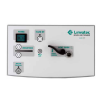
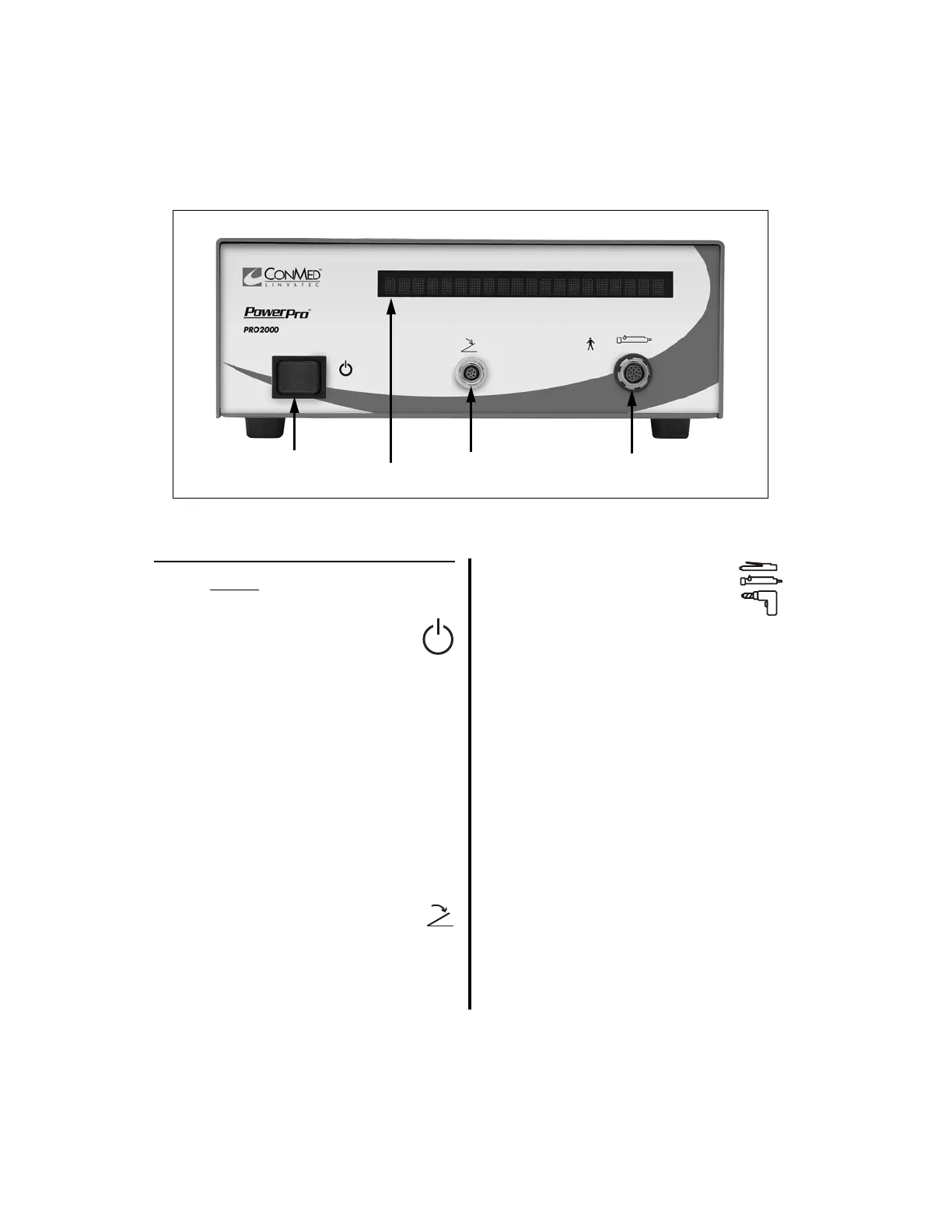
1.6.6 PowerPro Controller Front Panel
1. Standby Power Switch — To
activate the controller, place this
switch to the on position. To set the
controller to stand-by mode, place the
switch in the off position.
2. Display — Displays the following
information in text or graphical format;
user/error messages, instructions,
handpiece speeds, and operating modes.
Displays the actual speed while the
handpiece is operating and set speed when
the handpiece is inactive (See “2.1.3.9
Switch 5 - Display Mode Selection” on
page 45).
3. “FOOTSWITCH” Receptacle —
Accepts the footswitch cord
connector.
4. “HANDPIECE” Receptacle —
Accepts various handpiece cord
connectors, the Mini-Driver
Adapter (K501) or the APEX
Adapter (E9320).
NOTE: All handpiece and footswitch
receptacles and connectors are keyed to
prevent incorrect insertion. Likewise,
receptacles and connectors are color-coded to
easily recognize where to connect each cord.