4-10
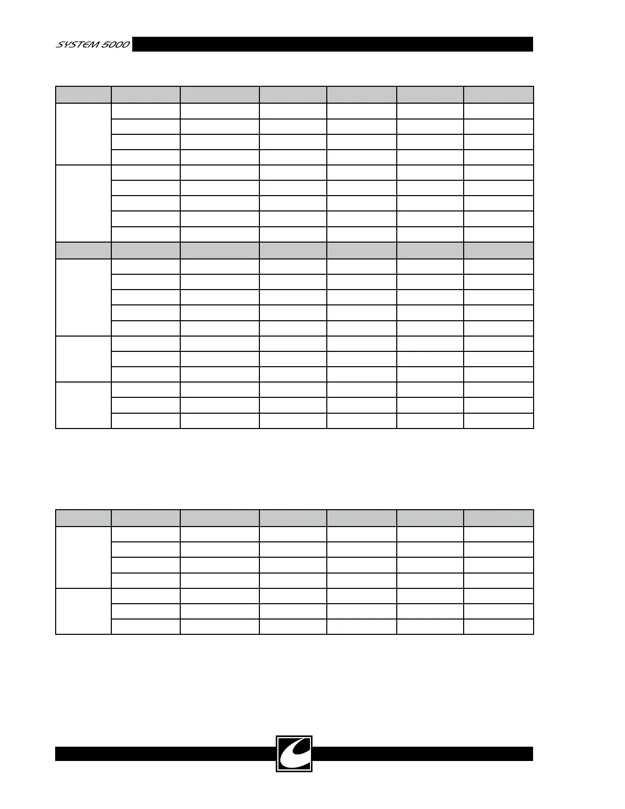
Table 4.2 Monopolar Coag Mode RF Output Power Accuracy
Mode Load (ohms) Power Setting Watts (min) Watts (max) Amps (min) Amps (max)
Spray 500 10 7 13.0 0.118 0.161
500 20 17 23.0 0.184 0.214
500 50 45 55 0.300 0.332
500 80 72 88 0.379 0.420
Standard 500 10 7 13.0 0.118 0.161
500 20 17 23.0 0.184 0.214
500 50 45 55 0.300 0.332
500 100 90 110 0.424 0.469
500 120 108 132 0.465 0.514
Mode Load (ohms) Power Setting Watts (min) Watts (max) Amps (min) Amps (max)
Pinpoint 500 10 7 13.0 0.118 0.161
500 20 17 23.0 0.184 0.214
500 50 45 55 0.300 0.332
500 100 90 110 0.424 0.469
500 120 108 132 0.465 0.514
Standard
pulse
500 10 7 13.0 0.118 0.161
500 20 17 23 0.184 0.214
500 60 54 66 0.329 0.363
Spray pulse 500 10 7 13.0 0.118 0.161
500 20 17 23 0.184 0.214
500 40 36 44 0.268 0.297
4) Disconnect the ESU tester from the unit.
5) Use test leads to connect the ESU tester to
the Bipolar Accessory outputs.
6) Perform the bipolar power tests indicated in
Table 4.3. This table only provides the mini-
mum number of points to be tested.
Table 4.3 Bipolar Mode RF Output Power Accuracy
Mode Load (ohms) Power Setting Watts (min) Watts (max) Amps (min) Amps (max)
Macro
Bipolar
300 10 7 13.0 0.153 0.208
300 20 17 23.0 0.238 0.277
300 50 45 55 0.387 0.428
300 90 81 99 0.520 0.574
Micro
Bipolar
50 10 7 13.0 0.374 0.510
50 25 22 28.0 0.663 0.748
50 50 45 55 0.949 1.049
4.6.4 RF Leakage Measurement
RF Leakage can present a hazard in the operating
room because electrosurgical currents can flow
to the patient and operating room staff through
unintended paths, which can cause injury. RF
leakage occurs because the total energy in the
output voltage waveform is provided with a con-
ductive path through stray parasitic capacitance
distributed within the generator and along the
length of the leads. Table 4.4 presents the allowed
RF leakage currents to ground.