Anvil Embedded System
Users Guide
www.connecttech.com
Document: CTIM-00066
Revision: 0.00
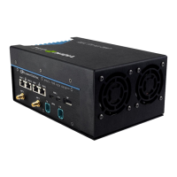
External Connector Summary
+10V to +36V Mini-Fit Jr. 6-Pin DC Power Input Connector
USB 3.2 Type-C Connector (Right most USB)
USB 3.2 Type-C Connector (Left most USB)
Dual RJ-45 Gigabit Ethernet Connector
Dual RJ-45 10Gigabit Ethernet Connector
Micro USB for connection to debug serial console
40 Pin GPIO/MISC Connector
GMSL 1/2 Quad Camera Connectors (JCB002 shown)
6 Pin Non-Isolated CAN Connector
External PCIe expansion connection
P – PWR BUTTON
R – RESET BUTTON
F - FORCE RECOVERY
Power, Reset and Force Recovery Pushbuttons (small pinhole
switches)
Antenna (LTE or cell Modem is defaulted to these locations)
Antenna (WiFi/BT is defaulted to these locations).