Operating Manual PG11 / PGE11 Page 17
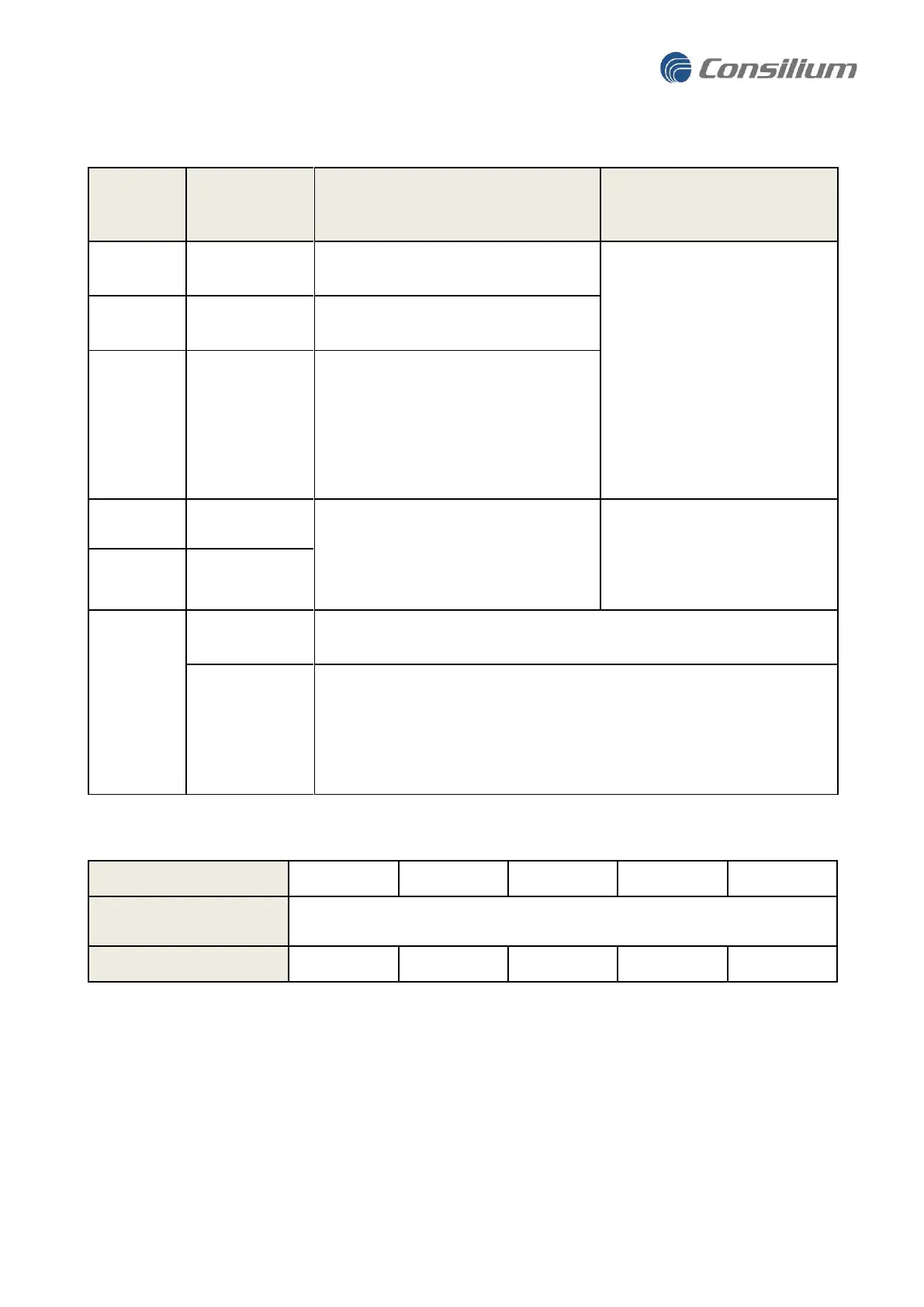
Table 1. Specifications of terminals.
Terminal
(detector
wire color)
Power, Positive
supply voltage
According to site requirements
and Table 2. Min. cross section:
0.14mm²
Max. cross section:
2.5mm² (Stranded)
4mm² (Solid)
Power, Supply
voltage return
Analog 0 - 20 mA DC signal overlayed
with a HART signal. Signals levels
described in
table 4
. The HART signal
is not interfering with the analog DC
signal and is described in a separate
chapter.
Maximum impedance 500
Ω
.
Two wires for connection to digital RS-
485 serial communication, Modbus
RTU.
Industrial communication cable
with shielded twisted pair.
Min/max cross section 0.14/2.5
mm² (stranded) or max 4 mm²
(Solid)
External grounding shall be used when the detector is installed in an Ex-
zone.
Normally not used. Shield of the cable is typically connected to instrument
earth in the central control cabinet and is normally not terminated at the
detector.
If extra RFI protection is required, and the installation's grounding
principles/regulations allow it, the shield can be terminated to local ground
via the internal earth point at the detector.
Table 2. Minimum voltage to PG11 shall be 18 VDC. Examples of cable and maximum length.
* For a nominal power of 24 V. Longer cable can be used with higher supply voltage.
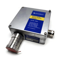
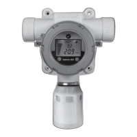
3.4.1 Booting up the Gas Detector
When turning on the power to the Gas Detector it has a boot-up time of 60 seconds. During this time the
Detector will run self diagnostics and if the indicator is configured to be active it will show yellow light. After
this boot-up time the Detector is ready to detect gas, but for a very precise testing of gas accuracy the
Detector should be allowed for another 20 minutes warm up time