Operating Manual PG11 / PGE11 Page 16
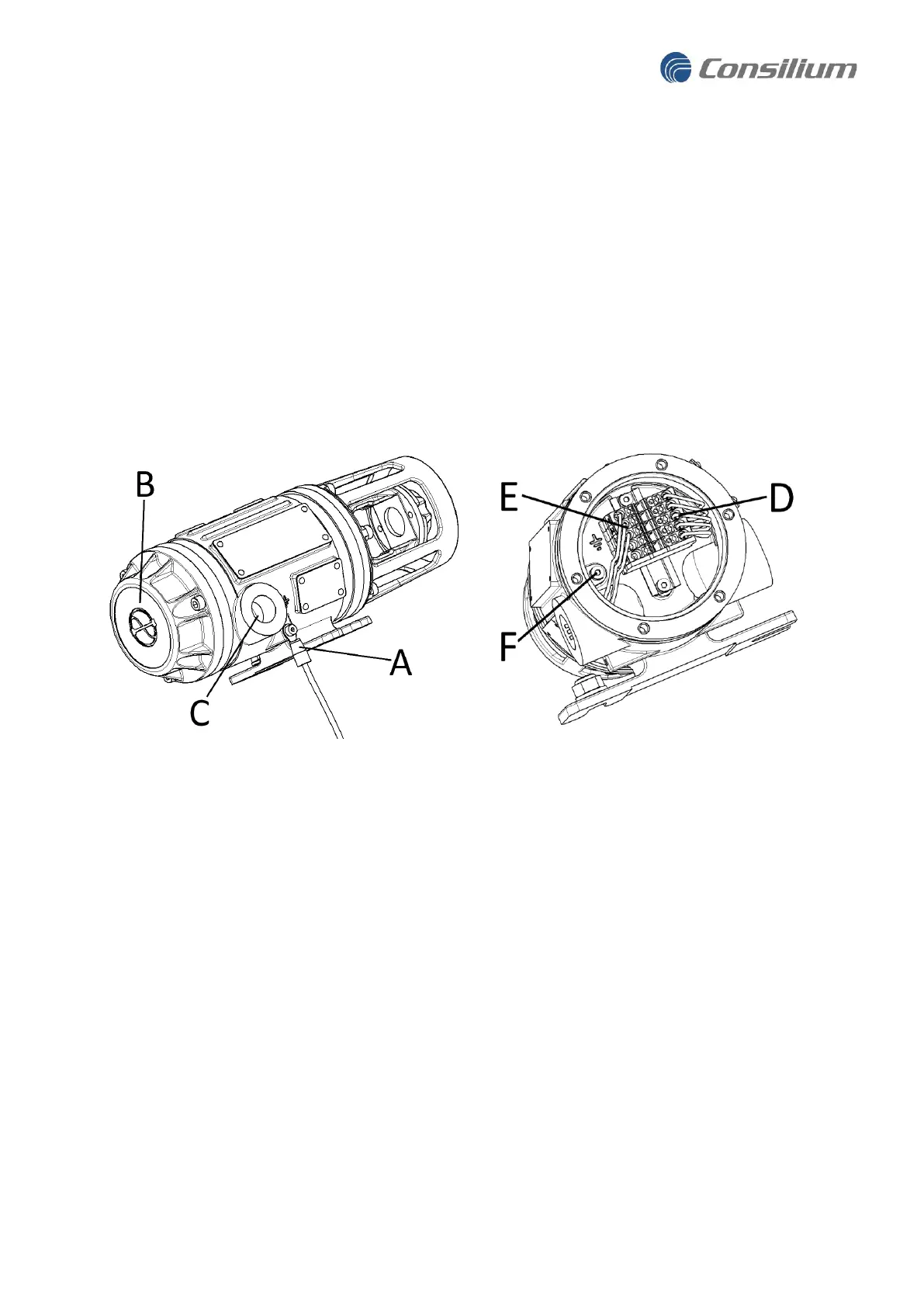
3.4 Electrical connections and Earthing
The PGxx11 chassis shall be connected to local
Clean Earth
. Use one of the two external Earthing points
(M4x5) illustrated in point A left drawing below using an
Earthing cable ring lug
. The electrical terminals are
located inside the rear lid in point B, opened by unscrewing the three screws fixing it. M20 cable entries C on
both sides of the Detector. The other dimensions M25, 1/2" NPT and 3/4" NPT are supplied on request at
order. The right side of the terminals D are occupied with internal wiring, and on the left side E are the
terminals (pin 1 at the top and pin 5 at the bottom) to be wired according to
table 1
. F is the internal Earth
point for an M4x4 screw for the connection of a cable lug.
To avoid the risk of corrosion, use quality fasteners for the connection of the earthing. Avoid the use
of aluminium, magnesium, titanium or zirconium. A lock washer or similar should be used to ensure
secureness of the electrical connection.
The termination compartment inside the rear lid is equipped with Phoenix Contact MPT 2,5 - 3248125 Push
in style connectors, accommodating wires of cross section 0.14mm² (AWG 26) to 2.5mm² (AWG14)
(4mm²/12AWG for single conductor wire). Wires should be stripped to expose min 8mm, max 10mm
conductor. Insert rigid conductors or conductors with ferrules into the conductor shaft. The contact spring
opens automatically and provides the required pressure force against the current bar.
The wiring of the Detector shall be done in accordance with
table 1
.