MANUALP/4000_SERVICE_0712 July2012
65
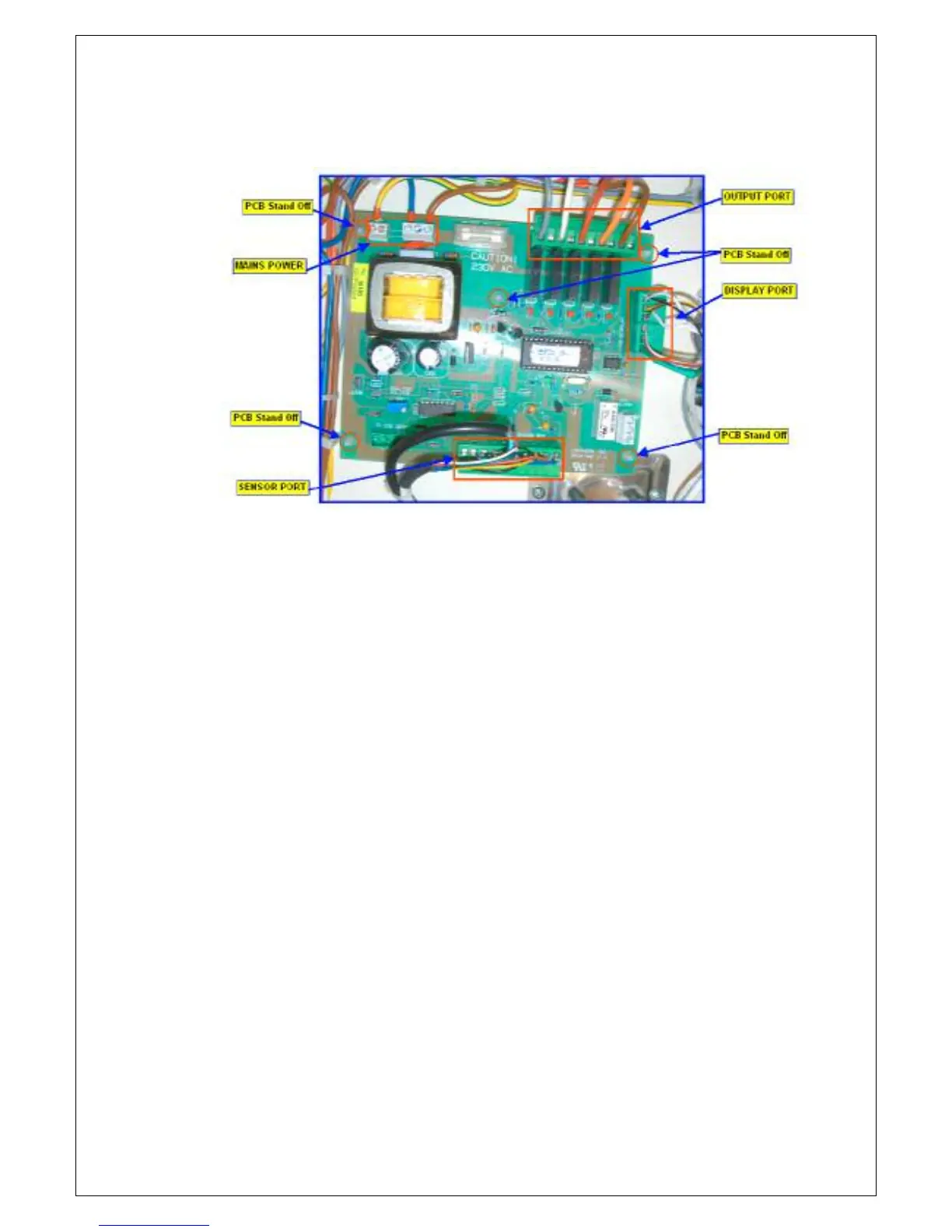
4. Below is the typical ZP22 Interface Controller Board layout showing the
locations of the different ports – sensor, output, display and main power
input.
5. Unplug all the wiring connections to the board. Take note of the
locations and orientation of the connections. Remove the board from
the PCB stand off.
6. Refitting of the board should be done in the reverse order as the above.
Please take note of the following:
a. Correct wiring connection must be observed.
b. Secure any loose wires with cable tie. Check for loose wires that may
have been missed, particularly the Earth wires.
7. BEFORE applying power to cabinet, carry out Insulation Test (use 500V
insulation tester) and Earth Continuity Test check (as per AS/NZS 3760:
In-Service Safety Inspection and Testing of Electrical Equipment).
The basic safety checks and tests on electrical appliances required by
AS/NZS 3760 are:
1. A visual check to ensure that there is no mechanical damage to the
supply cord, that controls etc... are in good working order and that
no parts are missing.
2. Earth continuity test.
3. Insulation resistance test.
In order to provide evidence of compliance, a label (signed and dated
by the person testing the equipment) may be placed on the tested
appliance.