MANUALP/4000_SERVICE_0712 July2012
9
SECTION 3 INSTALLATION
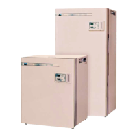
The CAT 4000 Mitre Series Incubators are designed to be installed into a
suitable well ventilated room with a preferred minimum clear space of at least
150mm on all sides to allow access for servicing. Mount the enclosure in its
final place ensuring that adequate space is allowed for the door to open. The
enclosure may be placed on the floor or a bench.
NB: On Tropicool and Cooled units ensure a space of at least 150mm is
allowed at the rear of the cabinet for air circulation – On Tropicool units ensure
that the unit can not be pushed too close to a rear wall. Locate the two stainless
perforated “butterfly wings” at the rear sides of the Tropicool unit and gently
bend to an angle of 90
o
.
The chamber requires a 240Volt 50HZ 10Amp Single phase EARTHED
electricity supply.
Total electrical load is upto 0.75Kw (4400C).
Maximum shelf loading is 30Kg/shelf, maximum total for cabinet is 100Kg.
The chamber should be thoroughly inspected for any signs of mechanical
damage that may have occurred in transit before any attempt is made to apply
power to the unit.
1) Connect a bottle of DRY FOOD GRADE CO
2
fitted with a two stage
Pressure Regulator set at 35kpa (5psi) to the Hosetail No 1 at the rear
of the enclosure.
2) If the enclosure is fitted with the automatic CO
2
CHANGEOVER option fit
the second gas bottle to Hosetail No 2. This bottle will automatically be
selected when bottle No 1 is empty.
3) Install the shelf guides in the desired positions. Slide the shelves into
guides.
4) On cooled / Tropicool units a large stainless steel or plastic tray is used to
both provide and collect water from the refrigeration system evaporator.
Ensure this tray is pushed firmly against the rear wall of the cabinet. If
elevated humidity conditions are desired partially fill the tray with distilled
or deionised water.
NOTE: The hosetail is a nominal ¼” brass barb. Typically use 6.0mm ID PVC
beverage tubing or similar to connect to the gas bottle regulator output. The
tubing should be secured to the hosetail using S/S hose clips.