5604 Input/Output (I/O) Module - Hardware Manual
October 19, 2007
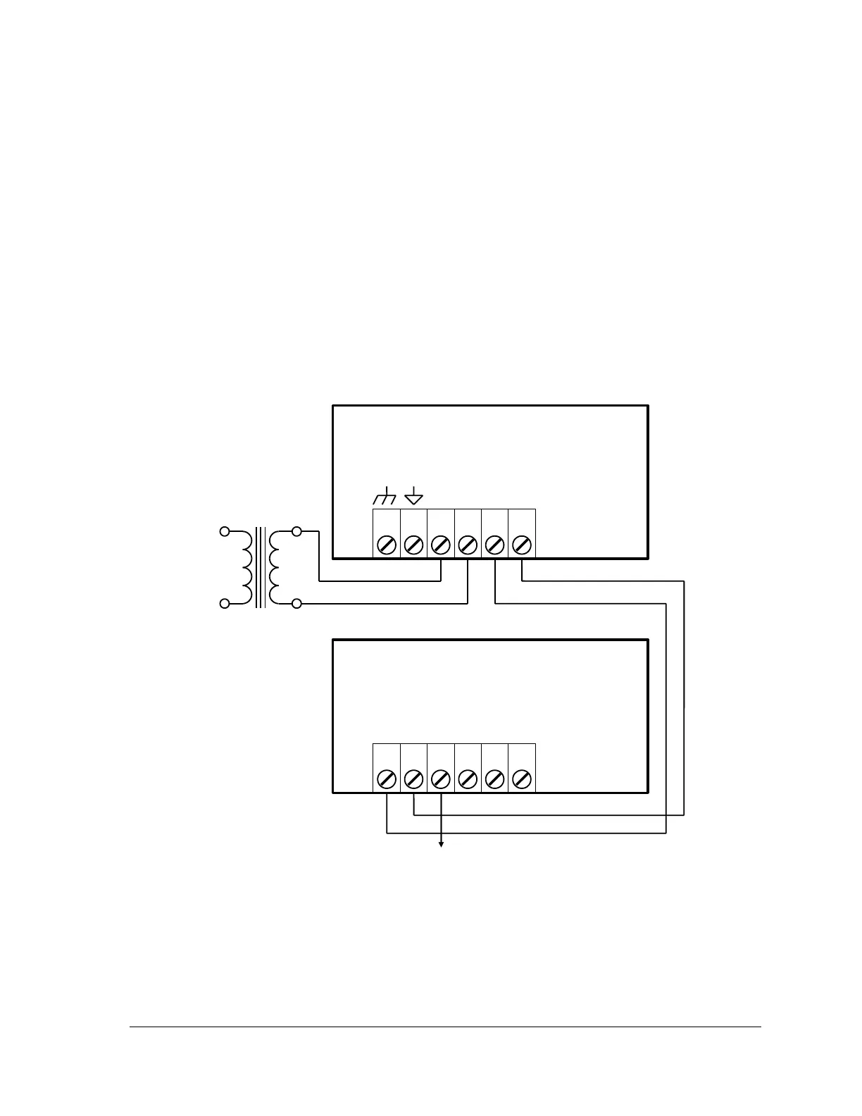
4.2.1 Recommended AC Power Supply Configuration
This configuration uses a single Class 2 16vac transformer to power the controller board and the
5604 I/O Module. 24V is available on the controller module connector P3. This is used to power the
analog circuitry for the analog input and output circuits on the 5604 I/O module.
Notes on this configuration:
The 24V-boosted output (VLOOP) can be switched on and off under the control of the
application program to save power to any loads connected to VLOOP.
The DC output of the controller board is unregulated and can be boosted to a stable 24Vdc on
the 5604 I/O Module under the control of the application program.
Only a limited amount of power is available from the controller. This configuration is not
recommended when a large amount of current is required at 24V.
The Controller Board DC Power terminal must be connected to the same power supply as the
5604 I/O Module DC Power terminals.
Controller DC output
boosted to 24V
Figure 2: Recommended AC Power Supply Configuration