5604 Input/Output (I/O) Module - Hardware Manual
October 19, 2007
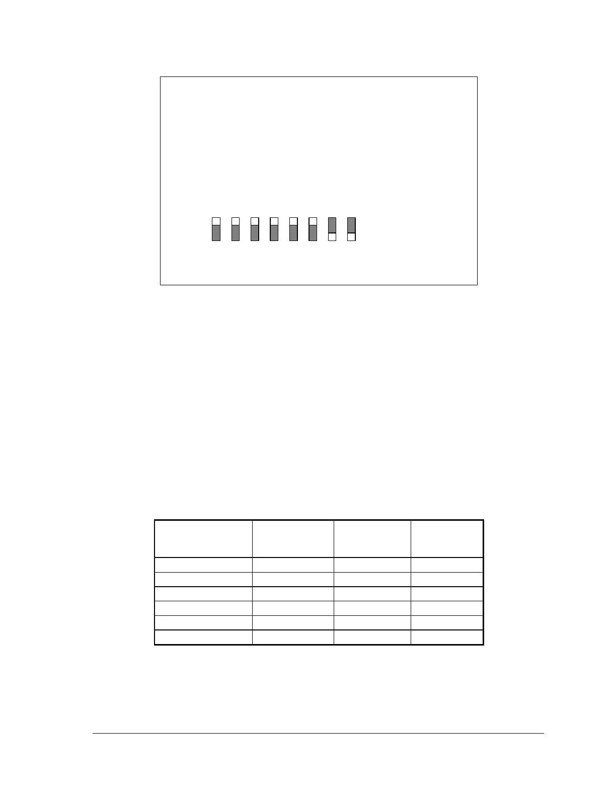
Figure 7: Analog Input Mode Settings
To select voltage mode, install the jumpers on the side labeled 5V. In the figure above, Analog
inputs 6 and 7 are configured for voltage mode.
5.2 Range and Resolution
Analog inputs channels 0 – 7 use a16-bit, unipolar, analog to digital (A/D) converter that measures
input voltages from 0 to 10V or currents from 0-20mA. In voltage mode, the input is represented by
a 15 bit unsigned real number. In current mode, the input is represented by a 14 bits unsigned real
number
Input resolution for channels 0-7 is:
0.305mV/count in voltage mode
1.22µA/count in current mode. There is 100% over range.
The following table shows the typical A/D output value for several input signals.
Analog input 8 is configured for voltage mode only. Voltage ranges of up to 32.768V are
measurable using a 10 bit A/D converter and represented with 15 bits of data. The input resolution
on this channel approximately 0.03V/count.