5604 Input/Output (I/O) Module - Hardware Manual
October 19, 2007
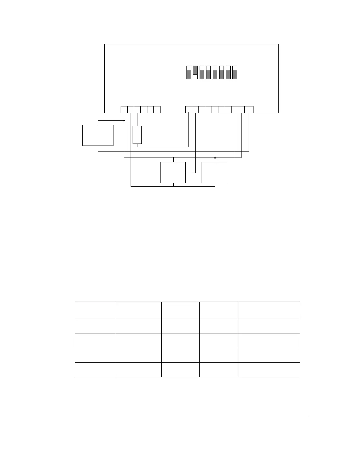
+
External 12 or
24Vdc Power
Supply
_
P3 – Power and Analog Outputs
Figure 8: Analog Input Wiring
5.4 Filtering and Response Timing
The 5604 I/O Module also provides internal digital outputs to control the filtering and response
times of the analog to digital conversion. Theses digital outputs can be controlled by the user
application to either maximize the filtering in noisy environments or minimize the filtering in
applications that require the fastest response times.
The following chart shows the response timing for the selectable filter settings.
Internal digital outputs 34 and 35 control the filter setting.
The 5604 I/O module may select 50 or 60 Hz line frequency for digital and analog input processing.
The Controller board Option Switch 3 selects the line frequency option.
155ms at 60Hz
185ms at 50Hz
85ms at 60Hz
85ms at 50Hz
45ms at 60Hz
55ms at 50Hz
30ms at 60Hz
30ms at 50Hz